Selecting a ladder tray by nominal width or cable count alone can leave a route overloaded, overcrowded, or impossible to install. A sound choice starts with the cable schedule, then checks structural loading, route constraints, environmental exposure, installation practice, and the supplier’s documented performance.
Key takeaways
- Use cable diameter, quantity, weight, bend radius, and separation to size each route.
- Calculate load per metre for the actual span, then check deflection and support spacing.
- Compare steel, aluminium, finishes, dimensions, and alternatives against the installation environment.
- Request drawings, load data, samples, inspection records, and a delivery schedule before ordering.
Turn the Cable Schedule into Tray Width and Separate Routes
Start with the cable schedule, not a nominal 300, 450, or 600 mm tray label. For each cable, record outside diameter, quantity, weight per metre, minimum bend radius, circuit function, and required separation.
Calculate occupied width from the actual arrangement: add cable diameters for a single layer, add clearances and dividers, then increase the result by the project’s specified spare-capacity percentage. Check that the remaining usable tray depth accommodates the arrangement without blocking ventilation or forcing cables between rungs.
Use the schedule to establish these inputs:
- Group cables by route and segregation requirement: power, control, instrumentation, data, and fire-alarm circuits may require separate trays or dividers.
- Calculate each group’s usable width from cable diameters, spacing, bend-radius constraints, and future capacity.
- Select rung spacing that supports the smallest or most flexible cable; otherwise cables can sag between rungs.
- Count runs by route length, fire-zone division, risers, and the width limit imposed by access, structural supports, and installation handling.
A large project therefore needs multiple parallel runs, not one oversized tray. Keep each route’s cable list and calculated width visible on the drawing so installers can identify spare capacity at every section.
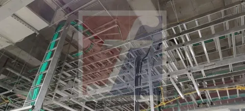
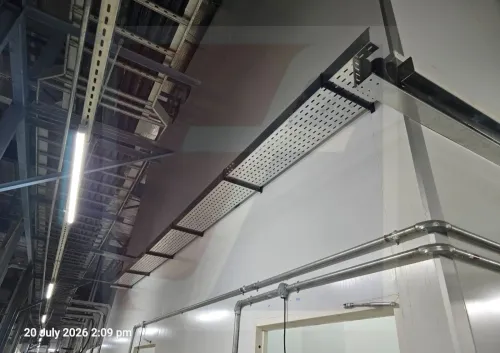
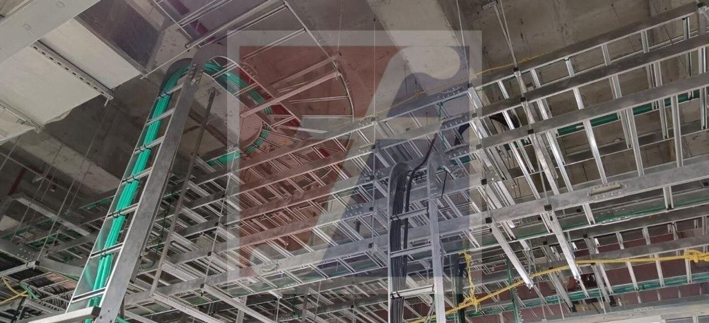
For ladder trays in Bengaluru, compare usable internal dimensions rather than catalogue width alone. Ask an industrial ladder tray manufacturer for a signed project load schedule, straight-section and fitting dimensions, splice-joint capacity, and support recommendations; a catalogue drawing does not prove suitability for your cable arrangement.
Select Capacity from Cable Weight, Span, and Deflection
Confirm capacity at the proposed support spacing, not from a catalogue’s standalone kg/m figure. Add the weight per metre of every cable to the tray’s self-weight, then include specified concentrated loads and environmental loads such as wind or snow where they apply.
- Calculate the design load in kg/m or N/m for the fully loaded route, including the required spare capacity.
- Use the manufacturer’s load-versus-span table at the actual span. A 1.5 m or 2.0–2.4 m spacing is not automatically acceptable; extending the span can sharply reduce capacity even when the tray is unchanged.
- Check the stated allowable deflection, such as span/200 or the project’s specified limit. A tray can survive the load yet sag enough to damage cable clearances or fittings.
- Verify the splice joint, rung, side rail, and support arrangement, especially where a joint sits between supports or a heavy cable enters at one point.
NEMA VE 1 links load classes to support spans and defined loading conditions, so do not transfer its rating to a longer span without engineering confirmation. IEC 61537 addresses mechanical performance, electrical continuity, and corrosion characteristics; it does not provide one universal load rating.
For ladder tray sizes in Bengaluru, ask an industrial ladder tray manufacturer for a signed project load schedule showing span, loading basis, deflection limit, tray construction, and support recommendations. A catalogue drawing alone does not prove capacity.
Compare Tray Dimensions, Materials, Finishes, and Alternatives
Compare usable tray width, clear side-rail depth, material thickness, rung spacing, finish, and tested span performance—not just nominal 300, 450, or 600 mm labels. Ladder tray sizes in Bengaluru are not a standard local catalogue: suppliers use different width increments, rail depths, gauges, rung spacing, and straight lengths.
| Application | Preferred construction | Check before selection |
|---|---|---|
| Indoor dry plant | Galvanized steel ladder tray; painted steel only where specified | Usable width, cable bend radius, rung spacing, and electrical continuity across joints |
| Outdoor or rooftop | Hot-dip galvanized steel with sealed cut edges and suitable covers | Drainage, UV exposure, monsoon water paths, corrosion allowance, and expansion-joint bonding |
| Chemical or coastal exposure | Stainless steel or a coating system proven for the named chemicals and atmosphere | Material compatibility, coating certificate, fasteners, and galvanic corrosion at dissimilar-metal joints |
| Mechanical impact or vehicle areas | Deeper side rails, heavier gauge, close supports, and covers or guards | Impact protection, concentrated loads, splice capacity, and deflection at the actual span |
| Small or flexible cables | Ladder tray with cleats, clamps, or a support liner | Prevent cables dropping between rungs and maintain restraint during pulling and faults |
| Alternative route | Solid-bottom tray, wire-mesh tray, conduit, or segregated trunking | Compare ventilation, drainage, shielding, access, bend space, and installation effort |
Ask the ladder cable tray supplier in Bengaluru for usable dimensions, straight-section and fitting drawings, splice-joint capacity, support recommendations, and material and coating certificates. Check IEC 61537 test evidence and the project load-versus-span table; a catalogue drawing alone proves neither capacity nor suitability.
Treat the metal tray as a support system, not automatically as the protective-earth conductor. Verify bonding across painted joints, expansion joints, and every splice, then provide separate bonding conductors where the electrical design requires them.
Check Route Fit, Cable Installation, and Protection Before Ordering
A proposed tray fits only after you check the route in three dimensions. Survey clear width, ceiling height, wall offsets, structural openings, fire barriers, access for jointing, and the space needed to lift cables over rungs without violating their bend radius.
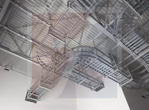
1. Mark every straight section, bend, tee, reducer, riser, and expansion joint on the route drawing. Check each fitting’s outside dimensions against beams, pipes, ducts, doors, and maintenance access. A catalogue centreline drawing will not reveal a clash at a congested support.
2. Check cable installation space, not only tray width. Maintain the cable manufacturer’s minimum bend radius at every turn, leave pulling and dressing access at joints, and add cleats or restraints where short-circuit forces could move power cables.
Small control, instrumentation, and data cables need clamps, covers, or a support arrangement that stops them dropping between rungs.
3. Divide routes where heat, signal interference, fire zoning, or maintenance rules require separation. Keep power away from sensitive instrumentation and data circuits unless the project’s segregation design permits a shared system. A wider tray is not a substitute for separate routes.
4. Confirm protection against the actual environment: rain and drainage outdoors, falling objects in plant areas, corrosive vapours, wash-down water, and impact from vehicles. Ladder construction improves ventilation and drainage, but it does not provide a closed mechanical barrier.
Before ordering ladder tray sizes in Bengaluru, ask an industrial ladder tray manufacturer to confirm straight and fitting dimensions, rung spacing, support locations, and splice clearance. Verify electrical continuity across joints separately; do not assume the metal tray is the protective-earth conductor. Use IEC 61537 documentation and the project earthing design to close that gap.
Evaluate a Bengaluru Supplier’s Documents, Samples, and Delivery Plan
Do not approve a catalogue drawing as proof of suitability. Request a project submittal that connects the proposed tray to your cable load, support span, route, and delivery date.
1. Ask for a signed load schedule stating cable weights, tray self-weight, design span, concentrated loads, allowable deflection, and the calculation or test basis. Require the load-versus-span table; NEMA VE 1 ratings are not unconditional ratings for longer spans.
2. Confirm straight-section and fitting dimensions: usable width, side-rail depth, rung spacing, material thickness, standard length, bend radii, reducer geometry, and tee dimensions. Check these against the approved layout, not only the nominal 300, 450, or 600 mm label.
3. Require splice-joint capacity, splice locations, support recommendations, anchor details, and the specified deflection limit. Excessive sag can damage bend-radius compliance, stress joints, retain water, or clash with nearby services.
4. Inspect a representative straight tray, bend, reducer, and splice assembly. Verify hole pattern, weld quality, edge finish, fit-up, coating appearance, and provision for cleats or restraints.
5. Obtain material certificates, coating or galvanizing certificates, routine production-inspection records, and batch traceability. Get a written delivery plan covering approved drawings, accessory quantities, packing, inspection release, and replacement of damaged parts.
Treat “ladder trays manufacturer in Bengaluru” and “ladder cable tray supplier in Bengaluru” as buying channels, not technical classifications. Give Fixotech Engineering Systems Pvt Ltd: Manufacturer of Cable Management Systems the same evidence before approval.
Related products
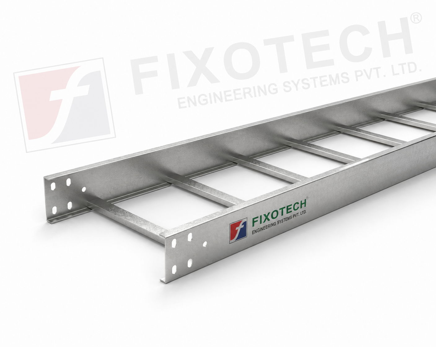 | LADDER CABLE TRAY Other common name in Cable tray industry is ladder tray. Simple design consisting of side rails with rungs connected. View product → |
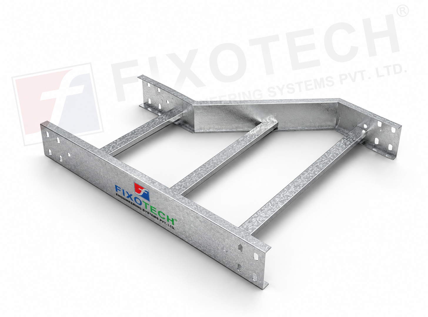 | LADDER CABLE TRAY REDUCER One particular kind of cable tray part made to make switching between cable trays of various widths or diameters easier is the reducer ladder cable... |
Frequently asked questions
How do you convert a cable schedule into ladder tray width?
List each cable’s outside diameter and quantity, group cables by circuit function and required separation, then add the specified spacing and future capacity. Do not choose a 300, 450, or 600 mm tray from the label alone.
How is ladder tray load capacity selected?
Calculate the cable weight per metre for the proposed route, then check that load against the tray’s span, support spacing, allowable deflection, and manufacturer load data.
Which ladder tray materials and finishes should you compare?
Compare galvanised or painted steel, aluminium, and stainless steel against corrosion exposure, indoor or outdoor location, cable weight, installation access, and the required finish specification.
What should you check before ordering ladder trays?
Confirm route dimensions, bends, risers, access clearances, cable bend radii, covers or protection, earthing details, and installation sequence against coordinated project drawings.
What documents should a Bengaluru ladder tray supplier provide?
Request dimensional drawings, material and finish details, load-versus-span data, inspection records, samples, packing information, and a delivery plan matched to project quantities.
Related products
 | LADDER CABLE TRAY One particular kind of cable tray made to make it easier to route cables at T-junctions in horizontal cable management systems is the ladder tee bend... View product → |
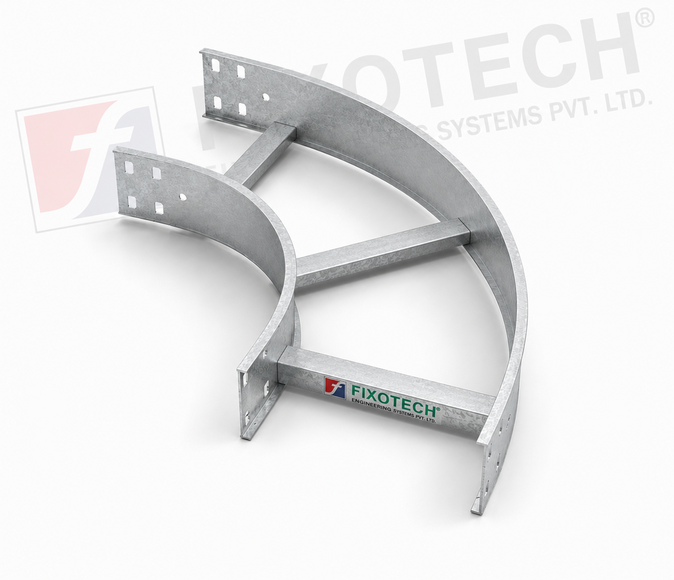 | LADDER CABLE TRAY The purpose of a horizontal ladder bend cable tray is to make it easier for cables to be routed around bends or corners in horizontal cable... View product → |
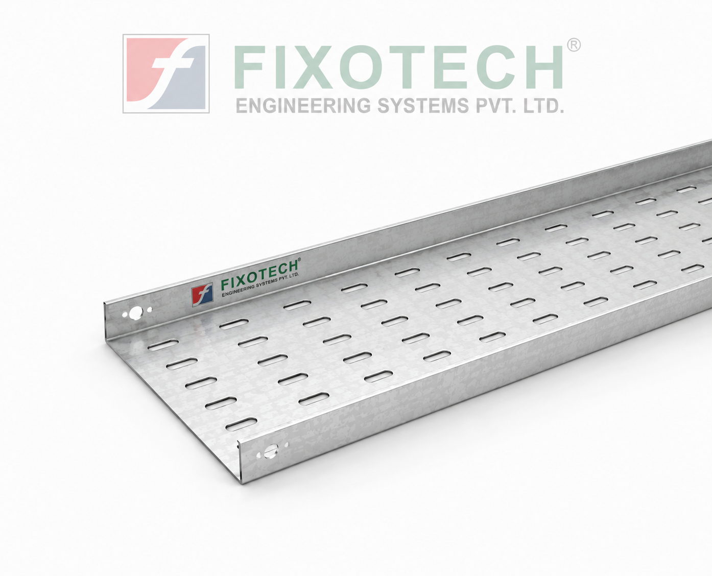 | PERFORATED CABLE TRAY Perforated Tray In electrical systems, a perforated cable trayeither with or without coversis a typical part used to support and arrange cables. View product → |
 | LADDER CABLE TRAY One particular kind of cable tray made to make it easier to route wires at cross junctions in horizontal cable management systems is the cross-bend... View product → |