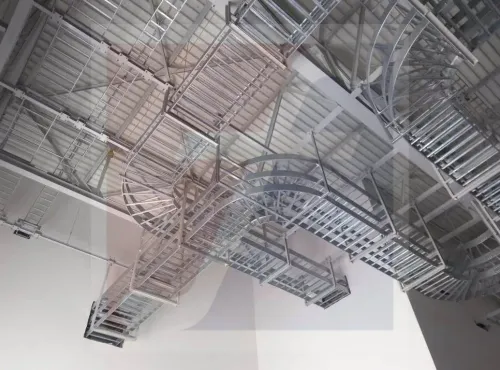
The choice between a tee bend and a cross bend depends on the number of cable routes, their orientation, and the space available at the junction. By checking the junction geometry, tray dimensions, cable bend radius, loading, support and splice details, you can specify the correct fitting instead of ordering by name alone.
Key takeaways
- Choose a tee for one branch and a cross for two branches or a reserved fourth route.
- Compare the fitting with separate bends, straight tray sections and couplers.
- Check tray family, cable minimum bend radius, load and junction support.
- Specify dimensions, material, finish, branch directions and accessories to your supplier.
Choose three-way or four-way junction geometry first
Choose a tee when one branch leaves the main route; choose a cross when two branches leave it or when you deliberately reserve a fourth direction. The decision depends on route count at the intersection, not simply on a 90-degree turn.
| Geometry | Tray paths | Best use | Trade-off |
|---|---|---|---|
| Tee | Three | One incoming or continuing main route plus one branch | Lower cost and less obstruction |
| Cross | Four | Two branches, or a deliberately reserved fourth route | More material, space and cable terminations |
In a cross bend cable tray comparison, an unused cross leg creates space to maintain, hardware to install and another cable termination to manage. Do not choose it for capacity alone.
Catalogs may label these parts bends, branches or fittings. State the geometry in the purchase request and identify every incoming and outgoing route.
- Specify horizontal tee or horizontal cross when the junction lies in plan.
- Specify inward vertical bend or outward vertical bend when the route changes elevation.
- State the junction centreline, branch-entry position, tray width, side-rail height and available clearance.
- Identify the required inside or centreline radius and the supports needed around the fitting.
“Tee bend or cross bend” is incomplete without orientation. A horizontal fitting, inward vertical bend and outward vertical bend have different shapes, clearances and support requirements; each also changes how cables enter, turn and terminate. Check fill separately on every route after the junction.
Compare a fitting with separate bends, straight sections and couplers
Choose a dedicated tee or cross when the junction needs a controlled cable path and repeated site cutting would create risk. Start with a plan view showing the junction centreline, route direction, branch-entry position, and clearance from walls, equipment and access ways.
Record nominal tray width and side height or side-rail depth before selecting the fitting.
| Option | What it means | When it applies |
|---|---|---|
| Dedicated tee | One branch leaves a continuing or incoming route | Use for one planned branch with a defined junction centreline |
| Dedicated cross | Two branches leave the main route, or a fourth direction is reserved | Use when four route directions are required; an unused leg adds space and hardware |
| Separate bends and straight sections | Individual horizontal bends connect through straight tray | Use for unusual angles, phased installation or layouts likely to change |
| Straight sections with couplers | Multiple straight pieces create a simple offset | Use to avoid special fabrication when extra length and abrupt branch transitions are acceptable |
Separate bends create more splice points and more opportunities for misalignment. Coupled straight sections consume length and can leave a sharp cable transition at the branch.
Check whether the branch enters at the centreline or toward one side. Measure the inside or centreline radius, not only the outside dimensions, and draw the horizontal or vertical orientation. Include working clearance for bolts, covers, dividers, splice plates and cables after supports are installed.
A fitting that fits the drawing but leaves no installation access is the wrong fitting.
Match the tray family and the cable’s minimum bend radius
A nominally matching fitting will mate and protect cables only when its tray family, geometry and cable path all match. Confirm width, depth, side-rail or sidewall profile, perforation pattern, flange shape and splice-hole layout; equal nominal width does not make fittings interchangeable.
| Tray family | What to verify | Failure if mismatched |
|---|---|---|
| Perforated-bottom | Hole pattern, flange and splice-hole positions | Plates misalign or cables encounter unsupported openings |
| Ladder tray | Rung spacing, rail profile and branch support | A perforated-tray fitting may leave gaps or sharp cable transitions |
| Transition between families | Approved adapter, bonding method and edge protection | The junction can loosen, cut insulation or lose electrical continuity |
Inspect the branch opening and cable-support surface for sharp edges, gaps and unsupported entry points. Match the fitting to the adjoining tray’s material and finish: hot-dip galvanized, pre-galvanized, aluminum, stainless steel and coated systems differ in corrosion resistance, weight, hardware and bonding treatment.
A perforated tray bend supplier should identify any permitted transition rather than assume compatibility.
Compare the fitting’s inside radius with the minimum bend radius stated by each cable manufacturer. Use the largest requirement for the cables or bundles passing through the junction; a catalog radius of 300 mm, 600 mm or 900 mm does not prove suitability. Check power, control, instrumentation and fibre-optic cables separately.
Calculate fill for the main route and every branch after the junction. Record these before approval:
- Cable pile-up at each exit
- Unsupported entry length
- Required radius for each cable group
- Edge protection or cover requirements
Specify support, load and cable control at the junction
A tee or cross needs its own support and load check; do not apply the straight-tray load table automatically. Request the fitting load and span data, or the tested system rating, for the actual support locations, cable placement and loading direction.
Show supports on every incoming and outgoing run, plus any support required directly at or near the fitting. Branch moments and concentrated cable weight can distort a junction that looks adequately supported on straight sections.
Plan cable control before installation. A crowded branch can force cables against edges, increase bend stress and block the adjoining route.
- Use a divider when power and control or instrumentation cables require segregation.
- Fit a cover where falling objects or environmental exposure threaten the cables.
- Install cleats or ties when the cable manufacturer or project specification requires restraint.
- Add edge protection where a cable crosses a cut edge or perforation.
- Keep the branch path clear so cables from one route do not pile into another or obstruct the exit.
- Treat splice hardware as part of the fitting system. Confirm the number and position of splice plates, bolts or couplers.
- Confirm whether the fitting arrives assembled, segmented or as a field-bolted kit.
- Verify electrical continuity with the manufacturer-approved bonding or splice method. Do not rely on painted or coated metal contact, loose hardware or mismatched metals to provide a reliable electrical path.
Turn the junction decision into a complete supplier specification
Send the cross bend or tee bend cable accessories manufacturer a specification, not a catalogue name. State each of these items in the request for quotation:
1. Tray type, nominal width and depth, side profile, perforation pattern, fitting orientation, branch angles, junction centreline, inside radius, material, finish and cover requirement.
2. Design load, support span, cable types, largest cable or bundle bend-radius requirement, fill for each tray segment and the governing project standard. Do not apply the straight-tray load table to the junction; request fitting load and span data for the stated support arrangement.
3. A dimensioned drawing showing every connection, branch-entry position, splice-hole layout and overall clearance. Include space for bolts, covers, dividers, cable installation and access around the fitting.
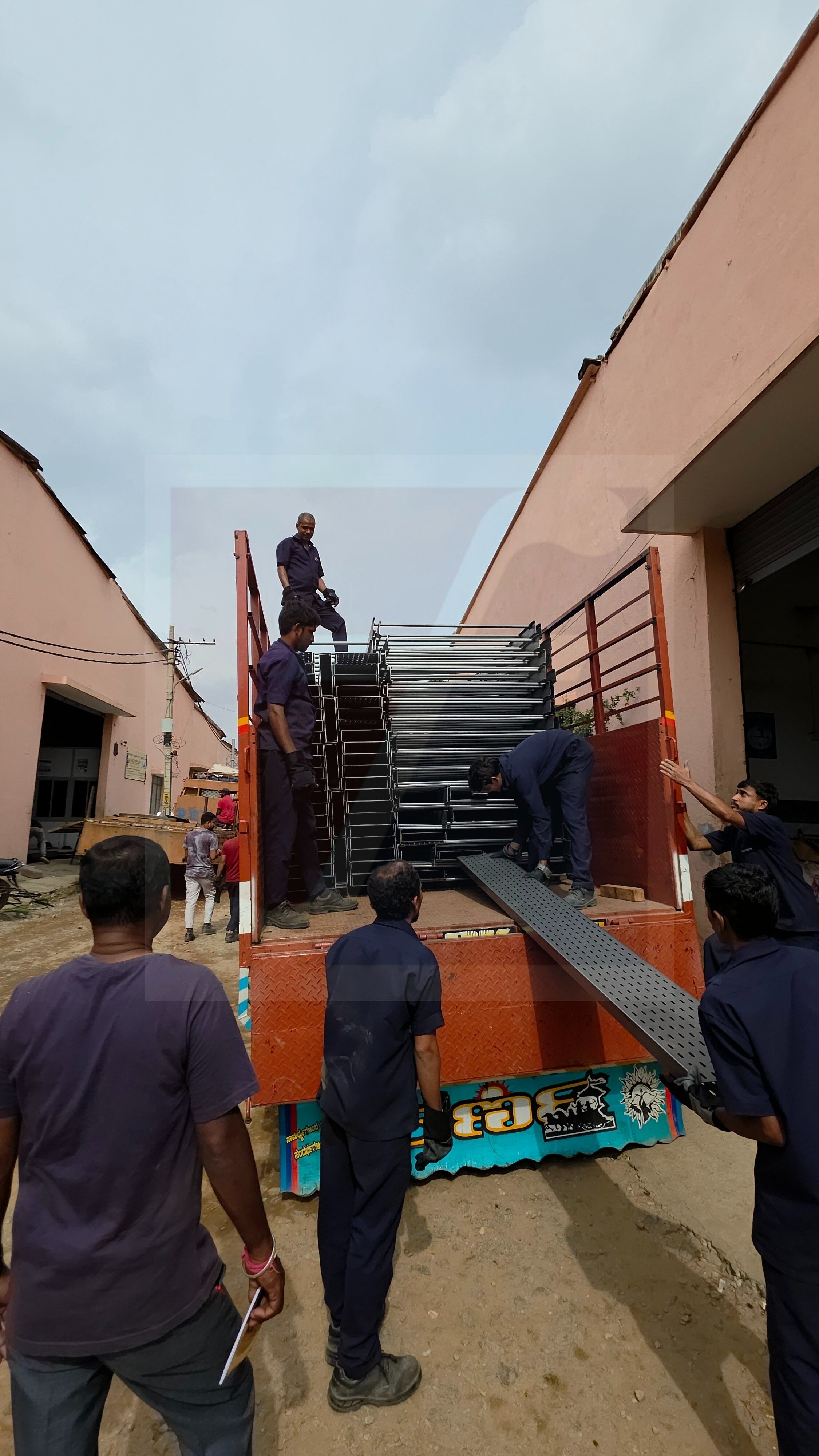
4. Splice-kit quantity, bonding method, delivery form and fitting load/span data. State whether the tee or cross arrives assembled, segmented or as a field-bolted kit.
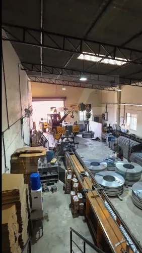
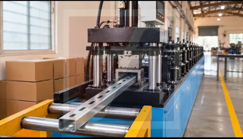
Fixotech Engineering Systems Pvt Ltd: Manufacturer of Cable Management Systems can be considered alongside other suppliers, but compare the submitted drawing and system data rather than the product label.
A perforated tray bend supplier must confirm that the fitting belongs to the same tray family as the straight sections, including side profile, perforation pattern, hole layout, material, finish and compatible hardware. Reject descriptions such as 90-degree tee, cross bend or perforated tray fitting when width, depth, radius, orientation, material and connection details are missing.
Related products
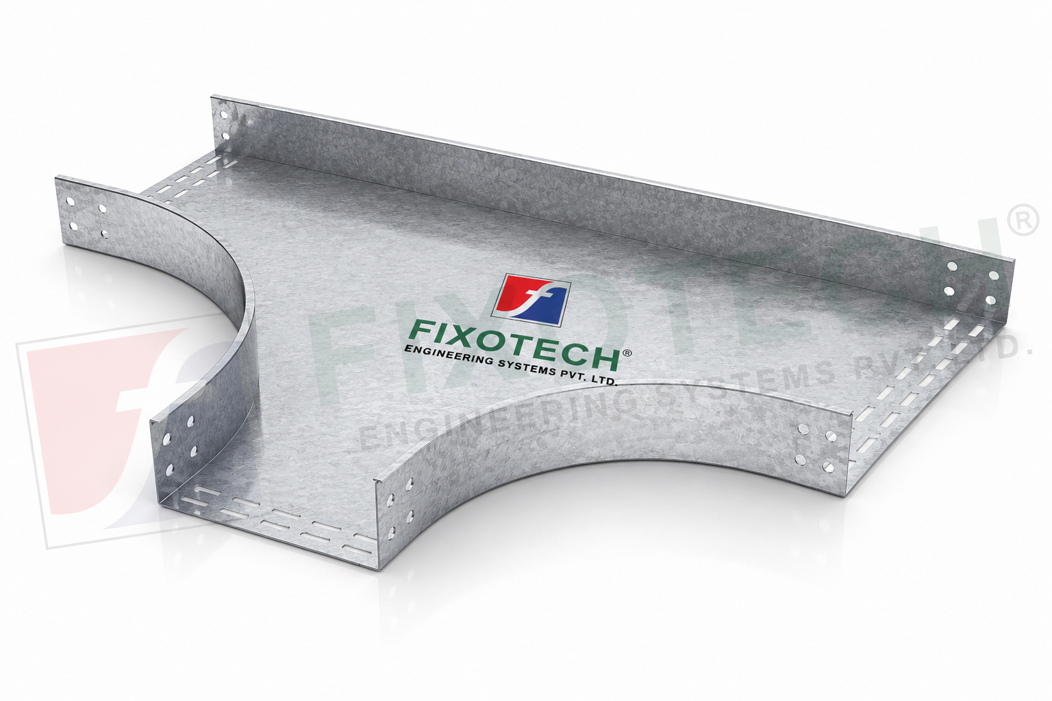 | PERFORATED CABLE TRAY In the context of cable trays, a “Tee Perforated Bend“ most likely refers to a particular part that combines the characteristics of a horizontal bend... View product → |
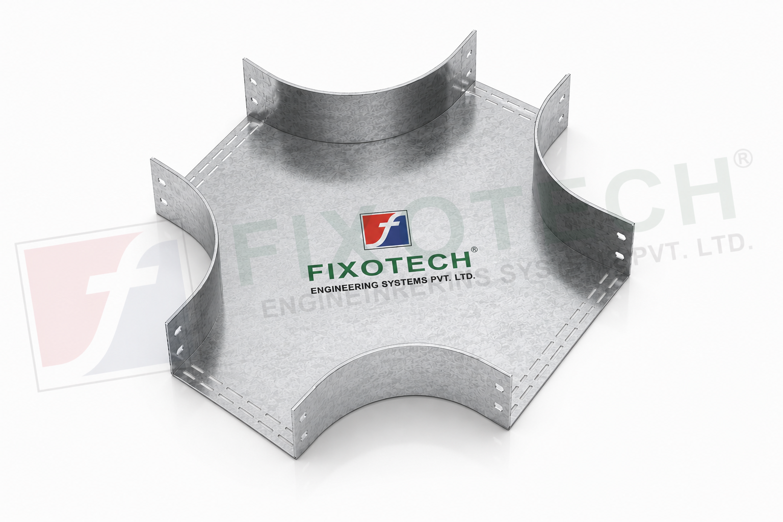 | PERFORATED CABLE TRAY It's possible that a “cross bend perforated type cable tray“ refers to a specific part that cable management systems use. View product → |
Frequently asked questions
When should you choose a tee bend instead of a cross bend?
Choose a tee when one branch leaves the main route. Choose a cross when two branches leave it or when you want a fourth direction available.
Is a formed fitting better than separate bends, straight sections and couplers?
Compare the fitting against separate components for installation time, joint count, alignment, cost, access and space at the junction.
How do you match a junction to the tray and cables?
Use the same tray family, width, side-rail height, material and finish, then confirm that every route preserves the cable manufacturer’s minimum bend radius.
What should a supplier specification include for a cable tray junction?
State the junction type, tray dimensions, branch directions, material, finish, load, support spacing, cable-control accessories and required couplers or fasteners.