A project order is not a request for a total number of metres. It is a coordinated schedule of tray widths, side-rail depths, perforation patterns, fittings, finishes, joints and delivery batches that must match the route drawings and the declared load basis. By following the production sequence, you can review a quotation, approve shop drawings and identify the details that prevent unusable or delayed tray deliveries.
Key takeaways
- Fix dimensions, load, supports, finish and route interfaces before cutting sheet.
- Match sheet purchasing and forming capacity to the project’s required delivery sequence.
- Inspect hole pattern, tray dimensions, thickness, finish and load-related documentation before dispatch.
- Mark each bundle by route, size and drawing reference for faster Kochi-site acceptance.
What information must be fixed before tray production starts?
Before purchasing material or cutting sheet, fix the tray width, side-rail height, straight-section length, sheet thickness, hole pattern, material grade, finish, cover requirement, support span and cable load. Provide route drawings showing bends, elevations, penetrations, equipment interfaces and field-measured offsets.
Release a quantity schedule, not one total metre figure. Itemise:
- Straight trays by width and length
- Bends, tees, crosses, reducers and vertical fittings
- Covers, splice plates and fasteners
- Delivery quantity and sequence by installation area
Fittings use separate blanks, tooling, jigs or formed assemblies. Omitting them from a perforated tray project supply can leave you with straight lengths that cannot be installed.
Stock and project-fabricated trays require different approvals.
| Option | What it means | When it applies |
|---|---|---|
| Standard stock tray | Existing dimensions and hole layouts follow a product schedule | Use when width, rail height, perforation and fittings match listed designs |
| Project-fabricated tray | Custom dimensions, unusual radii, non-standard perforations or interfaces are made to approved drawings | Require approval before cutting, especially for field offsets and equipment connections |
Agree the performance basis in writing before the perforated tray manufacturing process begins. IEC 61537 and NEMA VE 1 are separate bases; require the quoted edition, load class, support span, allowable deflection and test terminology. Do not transfer straight-tray data to a tee, reducer, bend or mid-span splice without confirmation.
Changes to hole pitch or remaining solid area can alter local stiffness and invalidate the load rating.
How is a project schedule converted into a manufacturing schedule?
An approved route schedule becomes a manufacturing schedule through a matrix that groups every item by width, side-rail height, thickness, material, finish and installation area. It then assigns material release, tooling, fabrication and dispatch dates.
1. Receive sheet or coil, verify the material grade, thickness and heat or batch number, then release only the approved material. Record the identification against the project schedule.
2. Decoiling and leveling prepare coil stock for accurate cutting. The manufacturer then selects the blank size and tooling for each straight tray, cover, bend, tee, cross, reducer and other fitting.
3. Cut blanks to length and make the holes by CNC punching or another approved method. Straight trays are commonly perforated before forming, while complex fittings may be cut after forming.
4. Roll-form or press-brake-form the tray and covers. Fabricate fittings using separate blanks, forming operations, jigs or welded assemblies; these steps often control lead time more than straight lengths do.
5. Freeze fitting quantities with straight-tray quantities before production. Route drawings must show penetrations, offsets, equipment connections, orientation, and left- or right-hand fittings before straight-tray fabrication begins.
6. Inspect dimensions, hole patterns, forming, welds, burrs and finish continuity. Pack bundles against the approved schedule, with splice plates and joint hardware identified by installation area.
7. Dispatch by installation area, not by isolated metre quantity. Each first delivery in a perforated tray project supply must contain the required straight tray, fittings and joint hardware.
This sequence is central to an industrial perforated cable tray supplier because an apparently complete shipment can remain unusable when one reducer, tee or splice set is missing.
How do perforation, forming and material choices affect the finished tray?
Hole pitch, hole width, web width and remaining solid area determine more than appearance. They control ventilation, drainage, cable ties, fastener placement and local stiffness. Enlarging holes or changing the pattern after load review can invalidate the declared rating even when tray width and sheet thickness remain unchanged.
Punched perforations suit repeatable production; CNC, laser or drilled holes suit approved non-standard patterns. Compare them by the result required:
| Method | Strength | Risk or limitation |
|---|---|---|
| Punched | Fast, consistent pitch and low unit time | Fixed tooling limits hole shapes and layouts |
| CNC or other machining | Accurate custom holes and offsets | Slower production, with burrs, heat marks or higher cost |
A perforated tray manufacturing process commonly follows this sequence:
- Identify the sheet or coil, then decoil and level it.
- Punch or machine holes before forming where the straight tray permits; cut and shear blanks to length.
- Treat cut edges, then roll-form straight sections or press-brake-form fittings.
- Weld complex or heavy bends, tees, crosses and supports where required.
- Deburr every edge and check dimensions, straightness, side rails, cracked bends, sharp corners and welds.
- Apply the specified finish, inspect coating continuity, pack by installation area and dispatch.
Material and finish must match the exposure, not a default choice. A perforated cable tray manufacturer in Kochi should treat coastal, wet, chemical, outdoor and high-temperature conditions as design inputs.
| Material or finish | Typical use and control |
|---|---|
| Carbon steel | Protected conditions specified by the project |
| Galvanized steel | Corrosion resistance; Z275 states coating mass, not service life |
| Stainless steel | Aggressive or hygienic environments |
| Aluminium | Low weight or particular corrosion performance |
| Pre-galvanized sheet | Economical standard work; protect cuts, welds and drilled modifications |
| Post-fabrication hot-dip galvanizing | Better coverage of fabricated surfaces; allow drain and vent holes |
| Powder coating or paint | Use the specified system; repair damaged edges and welds before service |
How are tray width, load capacity and quality checked before dispatch?
Before dispatch, the approved design is checked against the actual cable arrangement and installation conditions, not just the tray catalogue.
1. Confirm tray width from the project cable schedule. Account for cable fill, required separation, the largest cable bend radius, specified spare capacity and planned future additions. Use the project engineer’s governing specification; do not insert an invented universal fill percentage. Recheck width and side-rail height against the approved shop drawing.
2. Review load capacity for each item and installation condition. The declared value must state tray width, material, thickness, side-rail geometry, orientation, support span, joint position and allowable deflection. Do not transfer a straight-tray catalogue value automatically to a bend, tee, reducer, cross, cantilever run or mid-span splice.
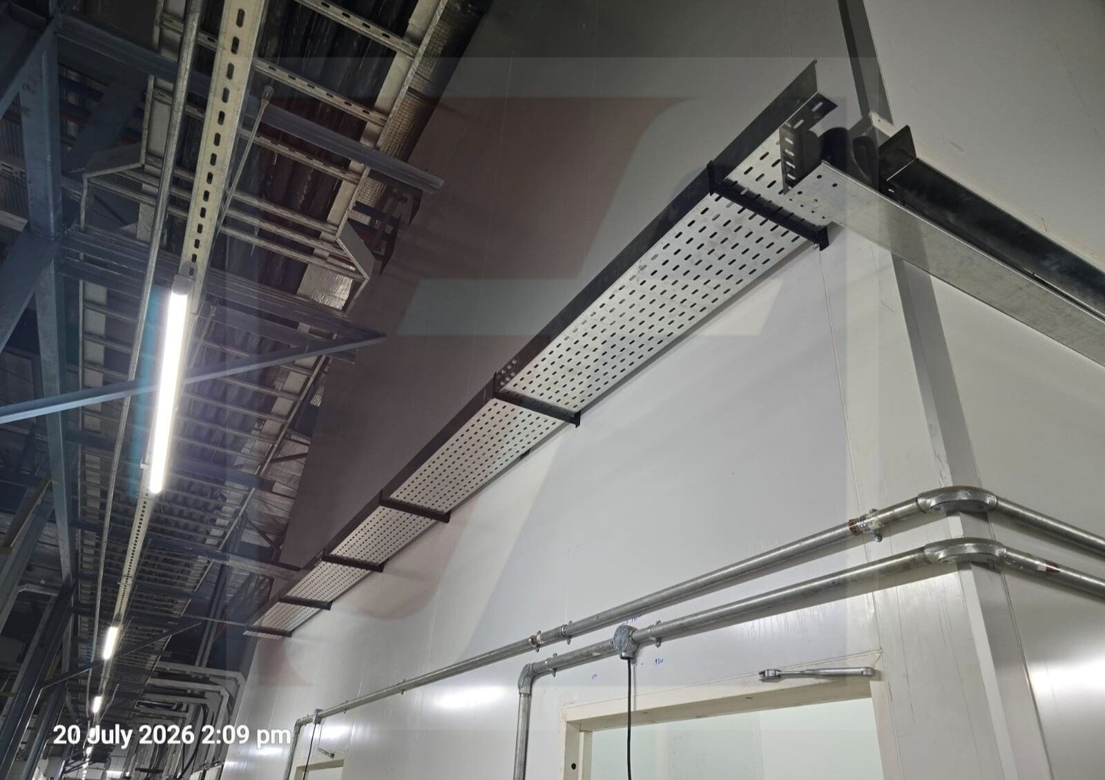
3. Inspect the perforated tray manufacturing process output for hole and overall dimensions, straightness, side-rail and flange geometry, burrs, sharp edges, cracked bends, forming defects, weld quality and coating continuity. Visual inspection cannot establish structural capacity.
4. Before release, an industrial perforated cable tray supplier should provide material certificates, coating or finish records, declared load/span data, inspection reports, approved shop drawings and joint installation details. Check that splice plates, connector bolts with stated grades, bonding provisions and compatible finishes match the system rating.
Mixing hardware from another system can alter joint strength, electrical continuity and corrosion behaviour.
How should a Kochi project order be packed, marked and accepted?
Acceptance starts with a bundle you can identify without opening it. For a perforated tray project supply, separate long straight sections, covers, splice plates, and left- and right-hand fittings. Mark each bundle with item code, width, side-rail height, length, finish, quantity, and installation area.
The packing list must follow the approved tray and fitting schedule, not a total-metre figure. Dispatch batches should match the site sequence, so each area receives its straight trays, bends, tees, reducers, covers, splice hardware, and fasteners together. Record shortages before installation begins.
| Control | Evidence to check | Failure prevented |
|---|---|---|
| Bundle identity | Label matched to schedule and installation area | Unusable or misplaced material |
| System completeness | Fittings, splice plates, bolts and bonding provisions | Delays caused by missing joint hardware |
| Technical approval | Drawings, IEC 61537 or NEMA VE 1 basis, load/span data | Unverifiable performance claims |
| Traceability | Material certificates, finish records and inspection reports | Unknown material or coating history |
This is how you assess a perforated cable trays manufacturer making trays for production in Kochi, a perforated cable tray manufacturer in Kochi, or an industrial perforated cable tray supplier.
Fixotech Engineering Systems Pvt Ltd: Manufacturer of Cable Management Systems is relevant when specification-based or customized production is required, but the evidence matters more than the name.
Before acceptance:
- Compare every bundle with the approved schedule.
- Verify finish, width, side-rail height and length.
- Check fittings, splice hardware and joint compatibility.
- Record deviations before site installation.
Frequently asked questions
What information must be fixed before perforated tray production starts?
Fix tray width, side-rail height, straight-section length, sheet thickness, hole pattern, material grade, finish, cover requirement, support span and cable load. Submit route drawings with bends, elevations, penetrations, equipment interfaces and field-measured offsets.
How is a project schedule converted into a manufacturing schedule?
Break the approved route schedule into tray sizes, fittings, covers, supports and delivery lots. Reserve sheet and forming capacity, then sequence production around installation zones, drawing approvals and the required site delivery dates.
How do perforation, forming and material choices affect the finished tray?
Hole size, pitch and open area affect ventilation, fixing options and strength. Forming controls side-rail geometry and straightness, while sheet grade, thickness and surface finish affect corrosion resistance, weight and handling.
How are tray width, load capacity and quality checked before dispatch?
Check the finished width, side-rail height, straight length, hole pattern, sheet thickness, finish and fitting dimensions against approved drawings. Confirm the specified support span and cable load basis through the project quality records.
How should a Kochi project order be packed, marked and accepted?
Pack sections and fittings by installation zone, protect finished surfaces, and mark bundles with size, quantity, route or area, drawing reference and batch details. Match the delivery note to the approved schedule before site acceptance.