Choosing a ladder tray by width or “heavy-duty” wording can produce the wrong support system, especially when cable size, span, weather exposure and fixing forces are unknown. By the end, you will be able to compare tray types, calculate a defensible tray specification and prepare an RFQ that exposes load, corrosion and installation risks before purchase.
Key takeaways
- Choose ladder tray for ventilation, access and regular cable support.
- Use span, cable weight and 40% usable area to size the tray.
- Separate power, control and instrumentation cables according to cable type.
- State dimensions, material, finish, covers, fittings and supports in the RFQ.
When ladder tray wins—and when another tray is safer
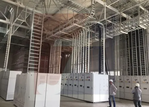
Ladder tray wins when you need easy cable installation, ventilation and direct support at regular intervals. Cables can be laid in from above, secured to rungs or cleats, and inspected without removing a solid bottom.
The ladder tray versus other cable trays decision changes when the cable is small, flexible or vulnerable to falling between rungs.
| Option | Main advantage | Choose it when |
|---|---|---|
| Ladder tray | Open access and ventilation | Power cables, heat-producing cables, long runs and frequent additions |
| Perforated tray | Continuous partial support with ventilation | Control cables, instrumentation and smaller cables that could sag between rungs |
| Solid-bottom tray | Full bottom protection and containment | Dust, falling-object exposure, electromagnetic shielding or cables requiring continuous support |
| Wire-mesh tray | Lightweight routing and fast installation | Short indoor runs with small, light cables and frequent route changes |
| Channel tray | Enclosed support for a limited cable group | One small control or instrumentation bundle needs separation from larger routes |
For a ladder cable tray in Kochi, select from the actual cable load and route, not a “heavy-duty” label. Sum each cable’s outside diameter area, add future capacity, and compare that occupied area with the usable internal tray area; leave room for ties, cleats and pulling access.
Check the manufacturer’s load table for the actual support span, rung spacing, splice position, cover, vertical orientation and concentrated loads. NEMA VE 1 figures change when those conditions change, while IEC 61537 evidence helps confirm mechanical load, continuity and corrosion performance.
Use a covered ladder tray where falling objects or containment matter; choose perforated or solid-bottom tray when continuous support is the safer choice.
Size the tray from span, load and usable cable area
A 600 mm ladder tray is not automatically stronger than a 300 mm tray. Ladder tray selection problems usually begin when buyers compare width, steel thickness or “heavy-duty” wording instead of the tested load at the actual support span.
Select the tray in this order:
1. Calculate cable occupancy from the outside diameter of every cable. For side-by-side installation, add the diameters, separation clearances and the specified future allowance; do not treat nominal width as usable width. Check the resulting cable cross-sectional area against the tray’s usable depth and side-rail height.
2. Add cable weight per metre, including future cables, then include covers, cleats, power-tap boxes and other attached equipment. A concentrated load at a riser or drop-out can exceed the uniform distributed load rating.
3. Specify the support span, splice position, installation orientation and deflection limit. Select the load class from the manufacturer’s test table for that exact configuration, using NEMA VE 1 data where applicable. A rating at 2.4 m spacing does not validate the same tray at 3 m spacing.
4. Choose rung spacing from the smallest cable diameter and its stiffness. Wide spacing suits large power cables; closer rungs or a bottom-support accessory prevent small control and communication cables from sagging. Verify the result on bends and vertical sections, not only on straight runs.
Match fixing and separation to the cable type
Fix the cable to the tray, not merely the tray to its support. Compare ladder tray versus other cable trays against the cable’s diameter, stiffness, bend radius and required protection.
| Cable type | Support and fixing | Arrangement |
|---|---|---|
| Power multicore | Rest on rungs; secure with approved cleats or ties at changes of direction, vertical runs and drop-outs | Keep separation from control and instrumentation circuits; support heavy local loads independently where required |
| Control | Use close-spaced rungs, tie bars or a bottom-support accessory | Prevent small cables sagging between rungs or falling through them |
| Instrumentation | Use a perforated-bottom or covered tray when cables need continuous support and protection | Maintain separation from power; cross power routes at approximately 90 degrees |
| Fibre-optic | Use smooth support, hook-and-loop ties and the manufacturer’s minimum bend radius | Do not crush, kink or place coils beneath heavy cables |
| Single-core power | Use cleats designed for the cable diameter, formation and prospective fault forces | Preserve the specified trefoil or flat formation; do not rely on loose ties for short-circuit restraint |
Wide ladder rungs suit large power cables but leave small control, communication and instrumentation cables unsupported. A cover, cable basket, perforated tray or solid-bottom tray is safer where falling objects, debris or cable containment matters more than ventilation.
Keep screened instrumentation cables away from high-current conductors and avoid sharing cleats that deform insulation. Route fibre separately when repeated maintenance or electromagnetic separation makes a common tray impractical. Verify every cleat, tie and clamp against the cable’s outer diameter and installation temperature; overtightening can damage insulation or fibre.
Check corrosion, covers, fittings and installation forces
A tray can meet its catalogue load and still fail after installation. Changing the support span, mounting it vertically, adding covers, or attaching heavy fittings alters the forces; NEMA VE 1 load tables apply only to defined spans and support conditions.
Select a ladder cable tray in Kochi from the actual layout, not its maximum uniform-load figure.
Treat these details as a site checklist:
- Calculate local loads at risers, bends, drop-outs, splice points and power-tap boxes. Heavy multicore cables, fibre-optic coils and vertical cleats can impose concentrated forces that a uniform distributed load rating does not represent.
- Specify base metal, coating process, coating thickness or mass, cut-edge treatment, fastener material and finish. In humid, salt-contaminated coastal air, dissimilar metals can create galvanic or crevice corrosion; stainless fasteners alone do not solve it.
- Use hot-dip galvanizing after fabrication for exposed routes when specified, or name the required stainless-steel grade or other corrosion-resistant finish. Do not assume an electro-galvanized indoor finish suits outdoor rain.
- Define whether covers are solid or ventilated, how they are retained, and whether supports and hold-downs resist wind uplift. A solid cover also changes heat dissipation and can retain water.
- Check every elbow, tee, reducer, riser and splice plate for compatibility, deflection and installation clearance. For vertical runs, verify cleat forces and fastener pull-out rather than applying a horizontal-tray rating.
Request IEC 61537 evidence for the assembled system’s mechanical load, electrical continuity, corrosion protection and component performance. These checks expose ladder tray selection problems before coating damage, loose fittings or a failed support appears on site.
Build an RFQ that lets a Kochi manufacturer quote the right system
Give every cable trays manufacturer in Kochi for ladder tray comparison the same RFQ schedule. A width-only quote cannot show whether two trays carry the same load, and “heavy-duty” is not a test rating.
- State cable type, quantity, outside diameter, weight per metre, present fill, future allowance and required installation access.
- Provide plan and elevation drawings showing straight runs, support span, splice positions, vertical sections, bends, crossings, termination points and expansion or structural movement joints.
- Specify the actual load case: uniform cable load, concentrated loads, support spacing, rung spacing, side-rail height, allowable deflection and reserve capacity. Request the manufacturer’s NEMA VE 1 load table for that arrangement, not its maximum catalogue figure.
- Identify indoor or outdoor location, temperature, humidity, salt exposure, chemical exposure and required corrosion class. Ask for base metal, coating process, coating thickness or mass, cut-edge treatment, fastener finish and splice compatibility.
- State whether covers, hold-downs, cable cleats, bonding jumpers and fire or falling-object protection are required. Include wind, seismic and vertical-load conditions where applicable.
- Request IEC 61537 test or conformity evidence for the assembled system, including mechanical load, electrical continuity and corrosion performance.
- Separate the commercial schedule into tray lengths, fittings, supports, joints, fasteners, covers, accessories, delivery quantities, lead time, warranty and installation exclusions.
Fixotech Engineering Systems Pvt Ltd: Manufacturer of Cable Management Systems should receive this same information as any ladder tray manufacturer in Kochi, so its quote can be compared on tested span performance, complete system scope and installed risk rather than price per metre.
Related products
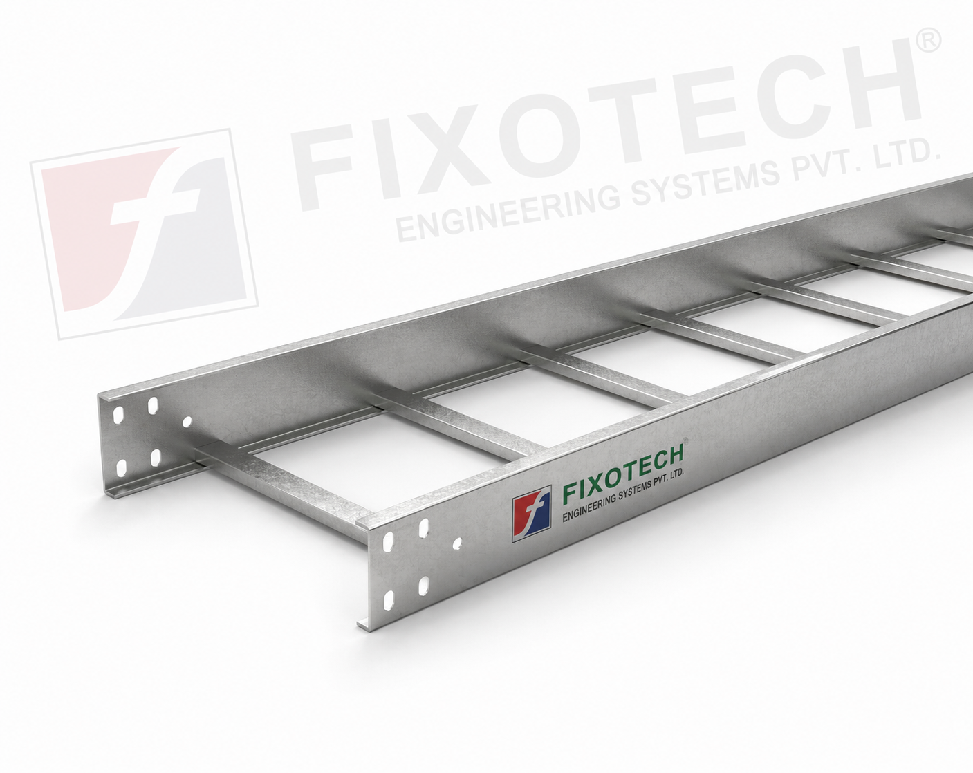 | LADDER CABLE TRAY Other common name in Cable tray industry is ladder tray. Simple design consisting of side rails with rungs connected. View product → |
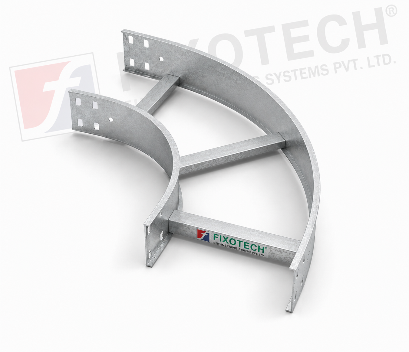 | LADDER CABLE TRAY The purpose of a horizontal ladder bend cable tray is to make it easier for cables to be routed around bends or corners in horizontal cable... View product → |
Frequently asked questions
When does ladder tray work better than a solid-bottom or perforated tray?
Ladder tray suits installations needing ventilation, easy cable laying from above, regular support and direct visual inspection. Choose another tray when small cables need continuous bottom support, debris protection or improved containment.
How do you size a ladder cable tray?
Size it from cable outside diameters, required separation, usable cable area, tray span and total cable weight. Leave room for installation and future circuits instead of filling the tray to its physical width.
How should cables be fixed and separated in ladder tray?
Use ties, cleats or clamps suited to the cable diameter, weight and fault forces. Keep power, control and instrumentation cables separated where the cable design or interference risk requires it.
What should a Kochi ladder tray RFQ include?
Specify tray width, side-rail height, rung spacing, thickness, material, finish, cover requirements, span, cable load, fittings, supports, separation and site conditions so the manufacturer can quote a complete system.
Related products
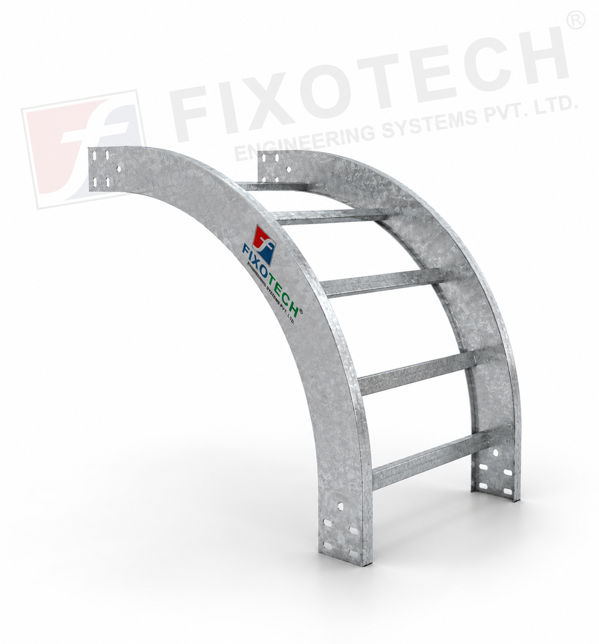 | LADDER CABLE TRAY A particular kind of cable tray called a vertical bent ladder cable tray is made to make it easier to route wires in vertical cable management... View product → |
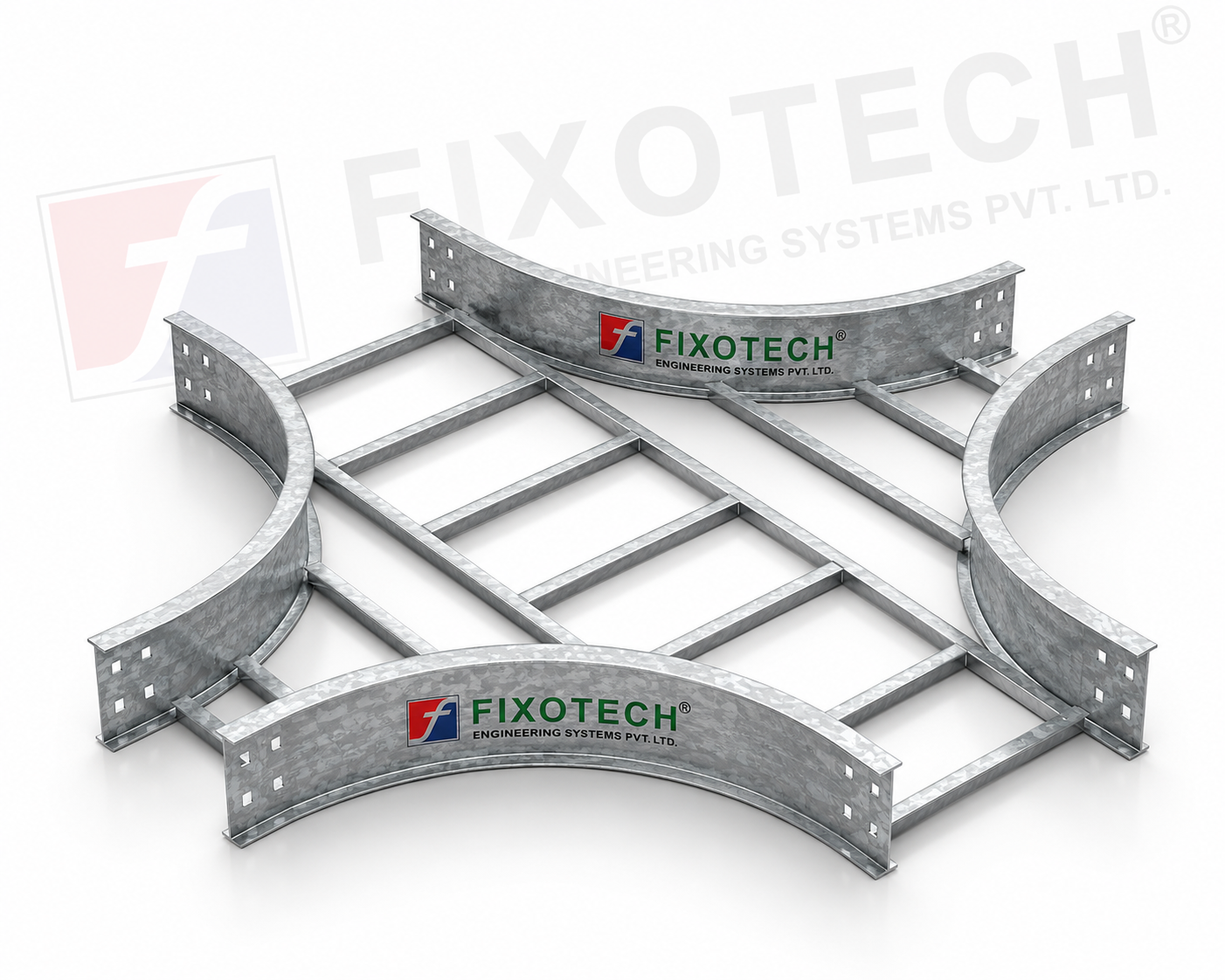 | LADDER CABLE TRAY One particular kind of cable tray made to make it easier to route wires at cross junctions in horizontal cable management systems is the cross-bend... View product → |
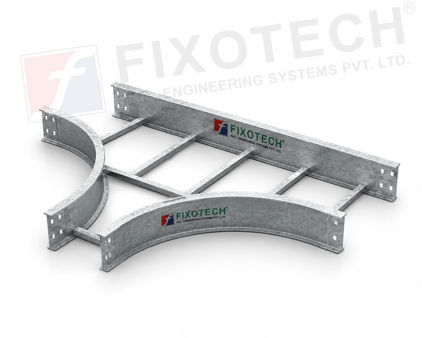 | LADDER CABLE TRAY One particular kind of cable tray made to make it easier to route cables at T-junctions in horizontal cable management systems is the ladder tee bend... View product → |
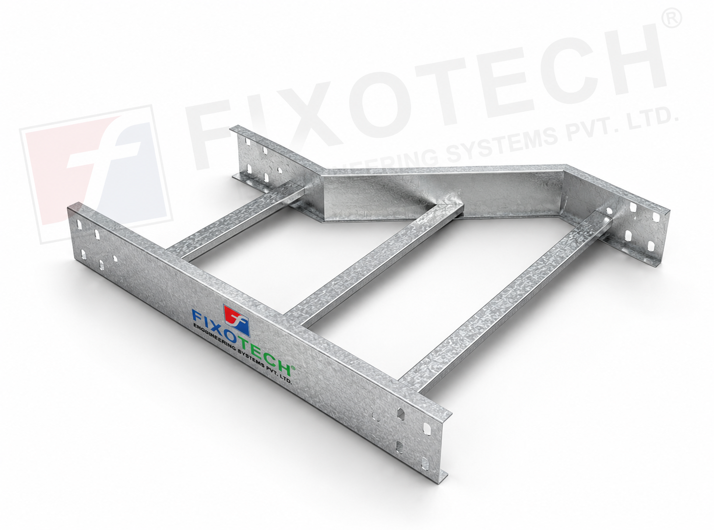 | LADDER CABLE TRAY REDUCER One particular kind of cable tray part made to make switching between cable trays of various widths or diameters easier is the reducer ladder cable... |