A perforated tray order begins with a cable schedule, route geometry and loading information, not just a width and quantity. By the end, you will know which technical details to submit, how the manufacturer converts them into drawings and production steps, and what to verify before dispatch.
Key takeaways
- Submit cable routes, cable sizes, support spacing and fittings with your schedule.
- Specify tray width, side rail height, sheet thickness, perforation and load class.
- Confirm coating, earthing, inspection documents and revision control before production.
- Count bends, tees, reducers, covers, supports and fasteners before approving delivery.
What information turns a cable schedule into a tray order?
A cable schedule becomes quoteable only when it describes the load, route and finished assembly—not just cable names and lengths. Submit the design package before asking for a price; otherwise the quotation may cover straight tray while leaving bends, supports or covers unresolved.
1. Cable data: cable type, outside diameter, quantity, total weight per metre, single-core or multicore construction, arrangement and required spare capacity. State the permitted fill basis and identify any heat-dissipation or ampacity constraints.
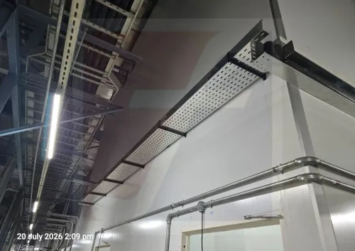
2. Route geometry: tray width and side-rail height if already specified, straight-run lengths, available installation width and height, elevations, horizontal and vertical bends, tees, crosses, reducers, risers and drop-outs. Include the installation orientation and access restrictions.
3. Support information: support spacing or span, support locations, splice positions, cantilever sections and any deflection limit. Request the manufacturer’s load/span table; nominal sheet thickness alone does not establish capacity. NEMA VE 1 or IEC 61537 may define the project’s performance reference.
4. Construction requirements: perforation pattern, hole size, tray thickness, standard straight length, required cut lengths, covers, splice plates, fasteners, earthing provisions, material and coating specification, plus indoor or outdoor exposure.
5. A coordinated bill of quantities: count straight sections separately from bends, tees, crosses, reducers, covers, joints and support hardware. This is the point where the industrial tray order process becomes a production schedule, allowing perforated tray manufacturing, nesting, packing and delivery to be priced accurately.
Include approved drawings, revision number, delivery location and required date. Ask the quotation to separate manufacturing, coating, inspection, packing and transport lead times.
How are tray dimensions, perforations and load capacity selected?
Tray width, side-rail height and sheet thickness are selected from cable size, cable weight, support span and installation space—not from the presence of perforations. The manufacturer converts those inputs into a tray section and support layout, then checks the result against a tested or calculated load/span table based on NEMA VE 1 or IEC 61537.
Submit these details for the industrial tray order process:
- Cable outside diameters, quantities, total weight per metre and arrangement
- Required cable fill, future capacity and cover requirement
- Straight-run lengths, bend radii, orientation, available clearance and support spacing
- Indoor or outdoor location, ambient exposure, material and coating specification
- Splice positions, fitting types and any equipment-entry or drop-out constraints
| Selection | Basis | What it does not prove |
|---|---|---|
| Width | Cable diameter, arrangement, fill calculation and expansion space | A wider tray is not automatically stronger |
| Side-rail height | Required cable containment, bend clearance and available installation depth | A taller rail does not replace a load/span check |
| Sheet thickness | Cable load, support span, deflection limit, material and corrosion allowance | Thickness alone does not establish the system rating |
| Hole pattern | Ventilation, fastening, drainage, splice-plate alignment and accessory interfaces | More open area is not proof of greater capacity |
| Supports and spans | Tested or calculated tray performance, splice locations and installation orientation | A catalogue load value may not apply to a different span |
Ask for the load/span evidence for the exact tray construction, support spacing and splice arrangement. The electrical designer must also confirm fill, heat dissipation and ampacity; a manufacturer’s physical fill calculation does not establish code compliance.
What happens during perforated tray manufacturing?
An approved drawing releases a production traveler: material grade, sheet thickness, tray width, side-rail height, hole pattern, straight length, fittings and specified finish are fixed before metal is cut. The drawing also identifies splice-hole positions and accessory interfaces, preventing a standard profile from being made with project-specific details omitted.
- Sheet or coil stock is received against the purchase specification. The manufacturer records the heat or batch number and checks the material certificate before releasing it to the line.
- Slitting, shearing or blanking cuts the stock into the required strip or flat blanks. The cutting plan controls length, scrap and grain direction where that affects forming.
- A CNC punch press or dedicated tooling creates the perforations, splice holes and other openings. Hole spacing, edge distance and pattern orientation are checked against the approved drawing.
- Roll forming produces repeated tray profiles at efficient volume. Press-brake work suits shorter runs, unusual gauges and heavily customized sections; incorrect forming settings can twist the base or leave unequal rail heights.
- The formed section is cut to final length, and splice plates, joining features or accessory details are fabricated. Operators remove burrs and round sharp edges so cables and installers do not meet exposed cutting edges.
- The specified surface treatment is applied, followed by drying or curing where required. The finish stage is separate from manufacturing time, so a cable tray production supplier should show it separately in the programme.
Inspection covers width, rail height, length, squareness, hole alignment, splice fit, burrs and visible damage. The inspector also checks coating records and retains material traceability before packing the tray with its fittings for dispatch.
How do coating, earthing and inspection requirements change the order?
Choose the coating from the installation exposure, then state it on the purchase order as a fabrication condition. “Galvanized” alone does not identify whether zinc was applied before or after perforated tray manufacturing.
| Option | What it means | When it applies |
|---|---|---|
| Pre-galvanized sheet | Zinc coating exists before punching and forming; cut edges and formed areas need review or repair | Indoor routes and controlled outdoor exposure where the specified coating remains suitable |
| Post-fabrication hot-dip galvanizing | The completed tray is dipped after fabrication, giving broader coverage but requiring drainage holes, venting, handling and dimensional checks | Outdoor, coastal, wet or aggressive environments needing stronger coverage |
| Stainless steel | Corrosion resistance comes from the alloy rather than a zinc coating | Chemical exposure, washdown or severe marine conditions where the selected grade is suitable |
| Paint, powder coat or zinc-rich repair | An additional or local protective system applied to the specified surfaces | Colour coding, indoor protection or cut-edge repair where the coating system is approved |
Ask the manufacturer to separate fabrication, galvanizing or painting, inspection, packing and transport lead times. Post-fabrication treatment can also affect splice-hole fit and tray dimensions.
Earthing changes with the finish. Confirm electrical continuity across joints, provide bonding jumpers where paint or an insulating joint interrupts contact, and specify the earth-conductor attachment point.
Accept the finished order only after checking:
- Material certificates and the ordered steel grade
- Width, side-rail height, length, squareness and hole pitch
- Smooth edges, absent burrs and safe handling surfaces
- Coating coverage and measured thickness or coating mass against the purchase specification
- Alignment of splice holes and accessory interfaces
- Applicable load-test evidence for the ordered span and section
How are fittings, revisions, packaging and delivery controlled?
Ordering straight lengths before resolving fittings creates the field problem: a tray run arrives, but its bend, tee or riser does not match the approved route. Freeze the route geometry and issue one coordinated bill of materials covering:
- Straight sections, including standard and cut lengths
- Horizontal and vertical bends, tees, crosses and reducers
- Risers, drop-outs and covers
- Splice plates, fasteners and support hardware
The approved drawing revision must appear on the order, fabrication drawings and packing list. Record every field change against a revision number; do not alter a fitting from a marked-up sketch without checking the new angle, radius, tray width and joining method.
A cable tray production supplier should confirm whether the change affects material, coating, quantity or delivery date.
Repeat batches need the original part numbers, hole pattern, gauge, coating specification and approved sample, not merely “same as last time.” A cable management systems manufacturer’s perforated tray for production in Kochi may quote standard profiles quickly, while custom perforations, stainless steel, special fittings or post-fabrication galvanizing add separate manufacturing and treatment time.
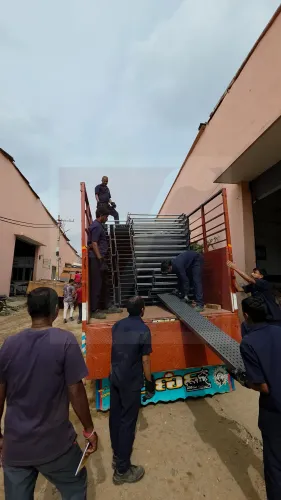
Fixotech Engineering Systems Pvt Ltd: Manufacturer of Cable Management Systems can use a controlled dispatch record to prevent substitutions between approved and packed parts. Label each bundle with project, route or drawing reference, part number, quantity, revision and destination; protect fittings and splice hardware from impact and mix-ups.
The packing list must reconcile with the bill of materials before loading, while the perforated cable tray supplier in Kochi separates inspection, packing and transport dates in the delivery schedule.
Related product
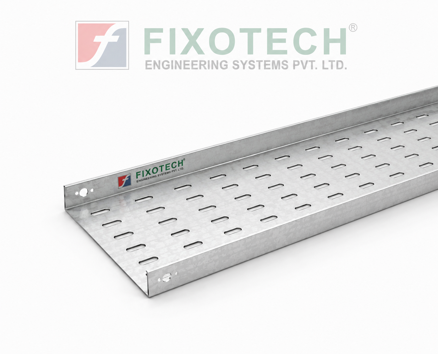 | PERFORATED CABLE TRAY Perforated Tray In electrical systems, a perforated cable trayeither with or without coversis a typical part used to support and arrange cables. View product → |
Frequently asked questions
What information turns a cable schedule into a tray order?
Provide cable sizes and quantities, route lengths, installation environment, support spacing, tray arrangement, covers, fittings and revision-controlled drawings.
How are tray dimensions, perforations and load capacity selected?
Select width from the cable fill and spare capacity, then confirm side rail height, sheet thickness, perforation pattern, support span and total cable load.
What happens during perforated tray manufacturing?
The manufacturer checks the approved drawings, cuts sheet, forms or bends the tray, creates perforations, produces fittings and inspects dimensions before finishing.
How do coating, earthing and inspection requirements change the order?
State the material and finish, such as pre-galvanized, hot-dip galvanized, stainless steel or painted steel, then define bonding points, inspection checks and required documents.
How are fittings, revisions, packaging and delivery controlled?
Use an approved bill of materials, revision number and packing list covering straight lengths, bends, tees, reducers, covers, supports and fasteners.