The right supplier must deliver more than straight tray lengths: you need tested load data, compatible fittings, support details, installation instructions and accessories that match the site. By the end, you can decide whether ladder tray suits your cable routes, check the manufacturer’s technical evidence and compare the real installation cost against other containment systems.
Key takeaways
- Choose ladder tray for high cable volumes on long, accessible routes.
- Verify load capacity using cable weight, span and support spacing.
- Check tray dimensions, fittings, bonding, earthing and cable clearances.
- Demand drawings, load tables, test reports and installation instructions.
When is ladder tray the right containment choice for a contractor’s project?
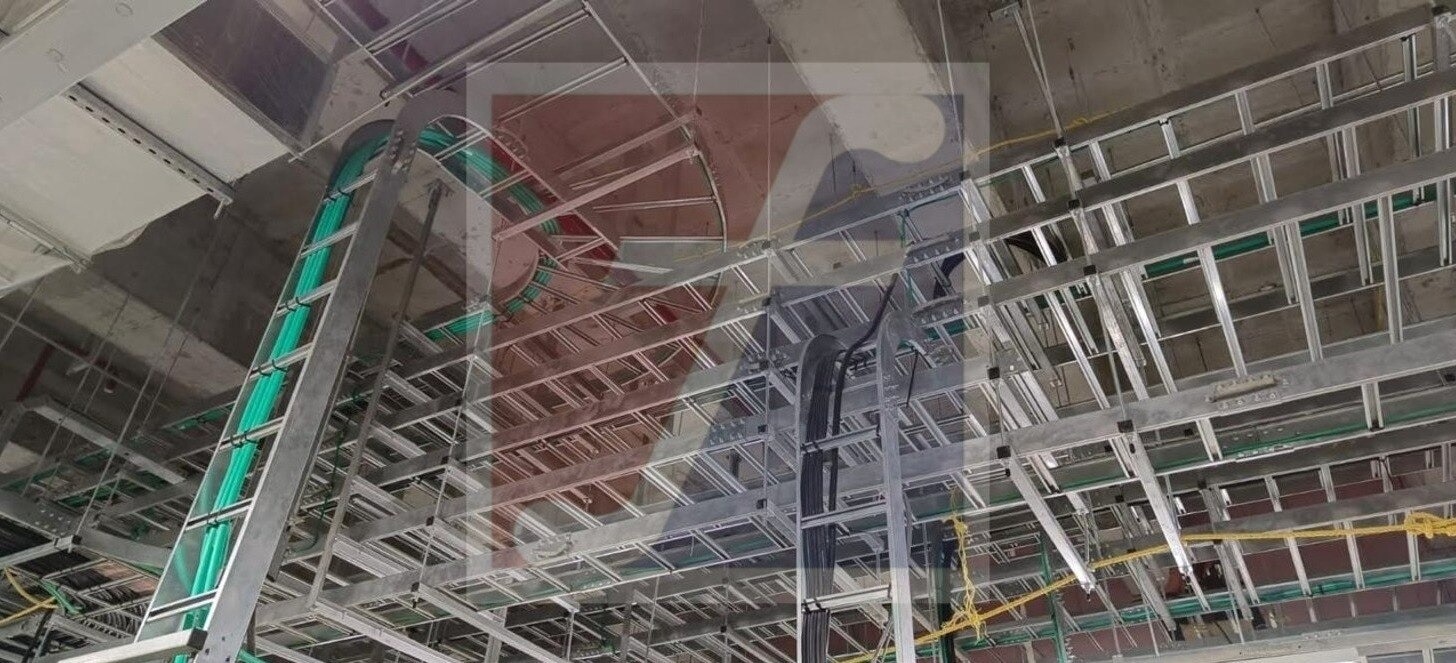
Choose ladder tray when a project carries high cable volumes along long, straight, accessible routes and needs ventilation, visibility, frequent additions or cable-cleat attachment. Its open construction suits industrial power distribution, but it does not protect cables like an enclosed raceway or conduit.
| Option | Strongest fit | Choose it instead of ladder tray when |
|---|---|---|
| Ladder tray | High-volume, ventilated power routes with accessible maintenance | The route needs open visibility and cable additions |
| Perforated tray | Small or moderate mixed-cable routes needing a more continuous base | Smaller cables need additional support or protection from snagging |
| Enclosed raceway | Concealed services and routes exposed to falling objects or heavy contamination | Cable protection and concealment matter more than ventilation |
| Conduit | Small control-cable routes, strict ingress protection or electromagnetic shielding needs | Each cable needs a sealed, shielded path |
| Wire mesh tray | Light communications or data cabling with quick access | Low cable loads and lightweight installation justify it |
Outdoor covers improve protection against falling objects, ice, UV exposure and unauthorized access. They also increase wind load, reduce heat dissipation and can change support spacing, restraint and anchoring requirements.
Check the cover’s effect on the complete installation before selecting it; a ladder tray for electrical contractors is unsuitable where those changes cannot be engineered or where contamination and water ingress remain uncontrolled.
How do you verify ladder tray load capacity and support spacing?
Use the installed cable mass per metre, not tray width or side-rail depth, to establish demand. Add the mass of the tray, covers and hardware where the load-table basis requires it, then add a recorded future-capacity allowance based on identified spare cables or a stated project percentage.
Convert the result to the units used in the manufacturer’s allowable working-load table.
| Check | Evidence to match | Decision |
|---|---|---|
| Span | Tested span and actual spacing | Do not transfer a 3 m rating to 1.5 m or 6 m without test or calculation evidence |
| Support arrangement | Trapeze, cantilever or other tested arrangement | Reject an unsupported arrangement |
| Connections | Splice location and orientation | Check whether the splice lies mid-span or over a support |
| Deflection | Stated deflection limit and load basis | Compare like with like |
| Extra load | Cover, concentrated cable, ice or other derating | Apply the stated reduction before accepting capacity |
Check support reactions at bends, tees, risers and other fittings; their loads do not behave like a uniform straight run. Verify vertical-run clamps or brackets, intermediate supports, and cleats against the cable weight and fault forces.
For long or moving routes, obtain details for expansion joints, sliding splices, bonding jumpers, seismic restraints and building-movement interfaces. An industrial ladder tray manufacturer should provide load calculations, reaction forces and installation limits for the exact configuration, not just a generic load chart.
What dimensions and installation controls should the contractor check?
Check the tray’s internal width, usable depth, side-rail height and rung spacing against the cable schedule, not just the largest cable diameter. Provide room for installation, inspection, heat dissipation and future work without forcing cables against the rails or fittings.
- Calculate cable fill using the governing code and project specification; do not treat the manufacturer’s fill or current-carrying figure as an ampacity calculation.
- Preserve each cable manufacturer’s minimum bend radius through bends, risers, drops and entries. A tight turn can damage insulation even when the tray has spare capacity.
- Maintain the specified separation between power, control, instrumentation and communication circuits. Install dividers or separate routes where the design requires them.
- Prevent abrasion at rungs with suitable supports, edge protection or approved accessories. Do not drag cables across sharp field cuts.
- Use cleats on vertical runs and on routes exposed to short-circuit forces. Space them according to the cable, fault-current and installation design.
- Avoid excessive tie tension on data cables; use the cable or tray system’s documented restraint method when one is provided.
A ladder cable tray contractor supply package must state compatible fittings, bend-radius treatment and fastening details, including splice orientation, bolt torque and allowable field cuts. Verify bonding jumpers across expansion joints, discontinuous fittings and coated interfaces; a bolted joint is not automatically a fault-current path.
Finally, apply the governing code’s rules for conductor count, grouping, ambient temperature, cable type and single-conductor arrangements. Tray capacity and conductor ampacity are separate checks.
What must a ladder trays manufacturer supply with the tray system?
A capable ladder trays manufacturer for electrical installation contractors supplies a complete, compatible system rather than only straight sections. The package must cover the route changes, supports, protection and electrical continuity that the site will actually require.
- Horizontal and vertical bends, tees, crosses, reducers and risers
- Splice plates, hold-downs, covers, drop-outs and clamps
- Support hardware, seismic restraints and bonding accessories
- Spare splice kits, fasteners and identifiable replacement parts
Request evidence for the exact rail height, rung spacing, material, coating, span and splice arrangement being purchased. IEC 61537 applies where the project uses that reference; NEMA VE 1 and NEMA VE 2 apply on projects that specify those North American standards. Neither replaces the governing electrical code, project specification or local approval requirements.
The supply file should include the applicable code edition, product listing or certification, load tables, material certificates, coating information and installation instructions. Do not accept a generic catalogue rating as proof for a different configuration.
The installation instructions must state:
- Splice orientation, bolt type and torque
- Field-cut limits and cut-edge protection
- Support spacing, support reactions and expansion-joint details
- Attachment methods and bonding arrangements
- Treatment at bends, risers and movement interfaces
An industrial ladder tray manufacturer becomes useful at project level by providing take-offs, fitting drawings, load calculations, support reactions and BIM or CAD files. Fixotech Engineering Systems Pvt Ltd: Manufacturer of Cable Management Systems should be assessed through these deliverables, plus coating data and replacement-part identification, not through straight-length availability alone.
Related products
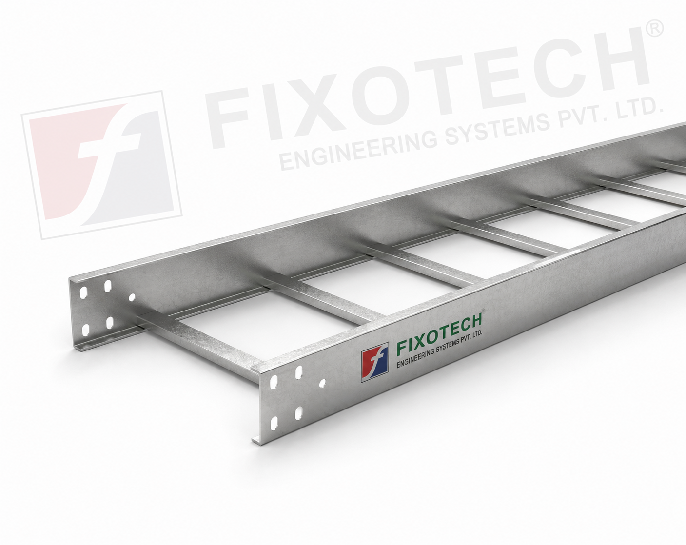 | LADDER CABLE TRAY Other common name in Cable tray industry is ladder tray. Simple design consisting of side rails with rungs connected. View product → |
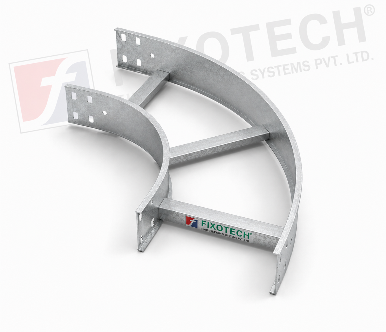 | LADDER CABLE TRAY The purpose of a horizontal ladder bend cable tray is to make it easier for cables to be routed around bends or corners in horizontal cable... View product → |
How should contractors compare supply offers before awarding the work?
Lowest price per metre is not the lowest installed cost. Compare a ladder cable tray contractor supply offer against the complete route, not only its straight lengths.
- Straight lengths, bends, tees, crosses, reducers and risers
- Fittings, splice kits, supports, threaded rod and seismic hardware
- Covers, bonding jumpers, clamps, drop-outs and hold-downs
- Field-cut protection, delivery time and spare parts
Material selection must match the exposure. A ladder tray for electrical contractors is not automatically suitable for every location.
| Material | Check before award | Failure risk |
|---|---|---|
| Pre-galvanized steel | Dry indoor route; protect cut edges | Rust at cuts or drilled holes |
| Hot-dip galvanized steel | Wet or outdoor route; inspect coating damage | Corrosion where the zinc is breached |
| Aluminum or stainless steel | Coastal, chemical or high-corrosion route; verify temperature limits | Pitting, galvanic attack or reduced strength |
| Buried or high-temperature installation | Obtain written suitability and installation limits | Coating breakdown, soil corrosion or heat-related capacity loss |
Confirm that every component belongs to one tested system, or obtain documented compatibility evidence. Mixed trays, fittings and splice hardware can invalidate assumptions about structural capacity, dimensional fit and electrical continuity.
Before awarding, record the load, span, dimensions, environment, movement details, accessory availability, inspection documents and handover requirements. Reject the offer if delivery excludes critical fittings, field cuts lack an approved protection method, or the supplier cannot identify replacement parts and provide installation, coating and bonding documentation.
Frequently asked questions
When is ladder tray the right containment choice for a contractor’s project?
Choose ladder tray for high cable volumes on long, straight, accessible routes where ventilation, visibility, future additions or cable-cleat attachment matter. Use enclosed raceway or conduit when cables need stronger protection from impact, dust or water.
How do you verify ladder tray load capacity and support spacing?
Add the installed cable weight, apply the project’s specified safety factor, and compare the result with the manufacturer’s load table for the planned support span. Confirm support spacing, deflection limits, splice locations and concentrated loads rather than relying only on tray width.
What dimensions and installation controls should the contractor check?
Check tray width, side-rail height, rung spacing, material, finish, bend radius, fittings, expansion provisions, cable separation, cover requirements and clearance from other services. Follow the approved layout and maintain bonding and earthing continuity across joints.
What must a ladder trays manufacturer supply with the tray system?
Request dimensioned drawings, material and finish specifications, load-versus-span tables, fitting details, installation instructions, fastener requirements, inspection documents and test reports where the project specification requires them.
How should contractors compare supply offers before awarding the work?
Compare the complete installed system: tray, bends, tees, reducers, joints, supports, covers, fasteners, bonding parts, delivery scope, documentation and lead time. Reject offers that quote tray length while excluding fittings or support hardware.
Related products
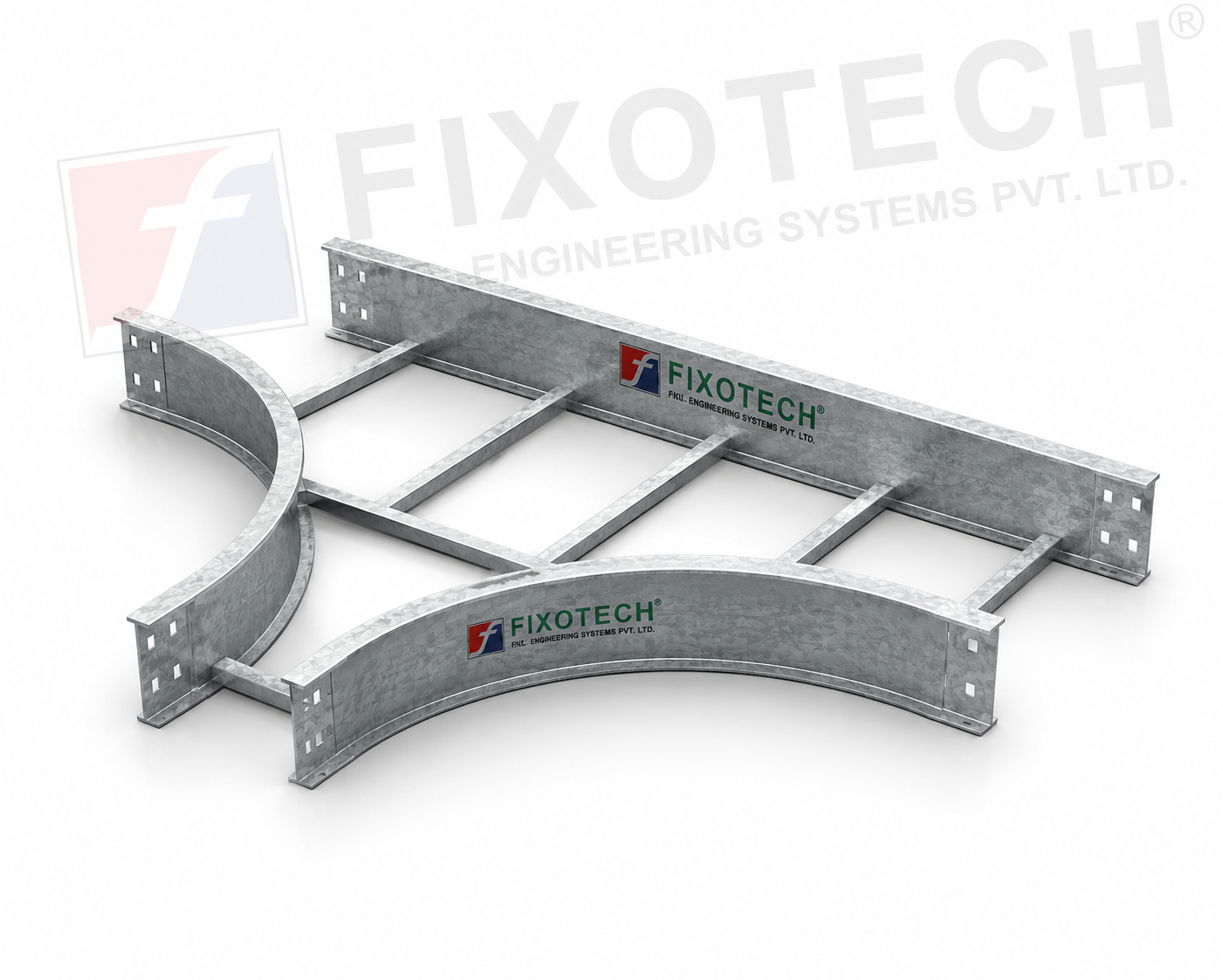 | LADDER CABLE TRAY One particular kind of cable tray made to make it easier to route cables at T-junctions in horizontal cable management systems is the ladder tee bend... View product → |
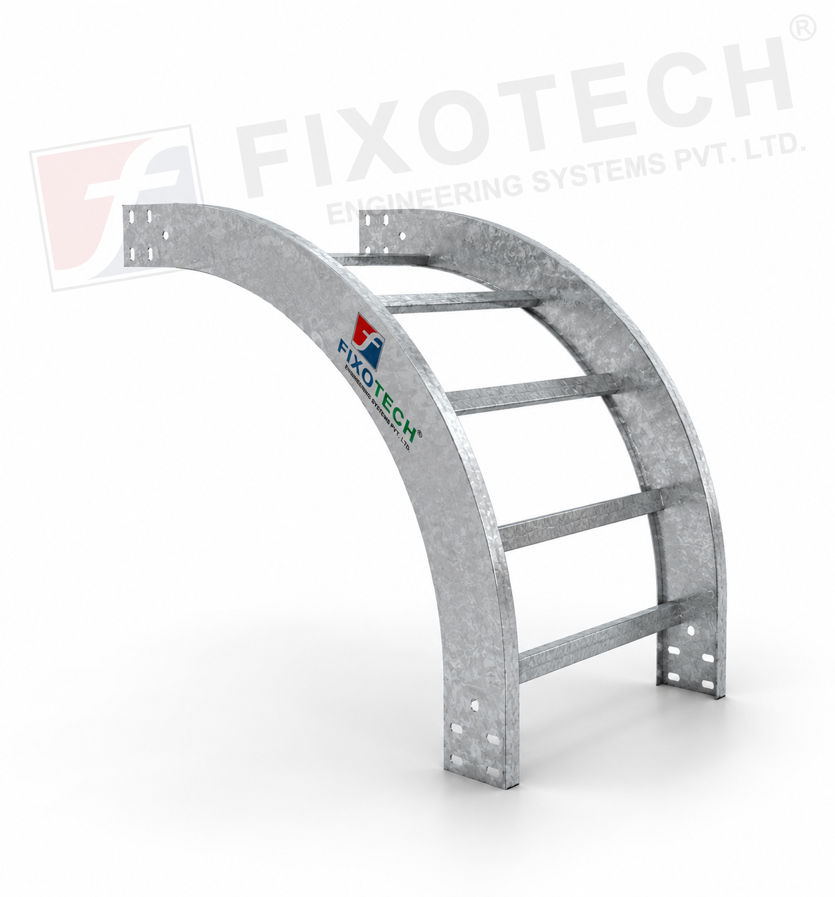 | LADDER CABLE TRAY A particular kind of cable tray called a vertical bent ladder cable tray is made to make it easier to route wires in vertical cable management... View product → |
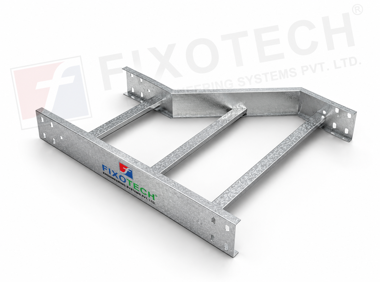 | LADDER CABLE TRAY REDUCER One particular kind of cable tray part made to make switching between cable trays of various widths or diameters easier is the reducer ladder cable... |
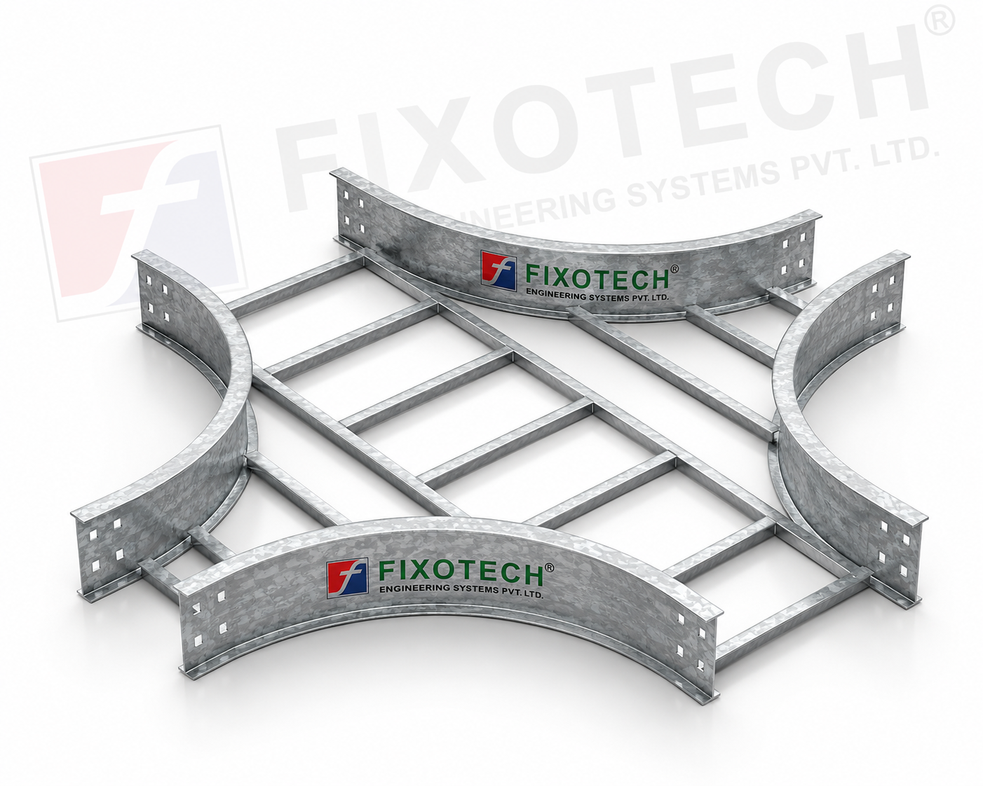 | LADDER CABLE TRAY One particular kind of cable tray made to make it easier to route wires at cross junctions in horizontal cable management systems is the cross-bend... View product → |