Tee-bend failures usually begin with a geometry, loading, or compatibility mistake rather than a single bad bolt or weld. You will be able to trace the fault from cable radius and branch layout through manufacturing inspection, support design, material selection, and site acceptance.
Key takeaways
- Measure the inside throat and radius, not only the outer rail.
- Check cable minimum bend radius before approving a tee fitting.
- Verify fill, cable weight, support spacing, and branch loading together.
- Record dimensions, materials, finish, bonding, and test evidence in acceptance files.
The Tee Geometry Can Force Cables Into a Damaging Path
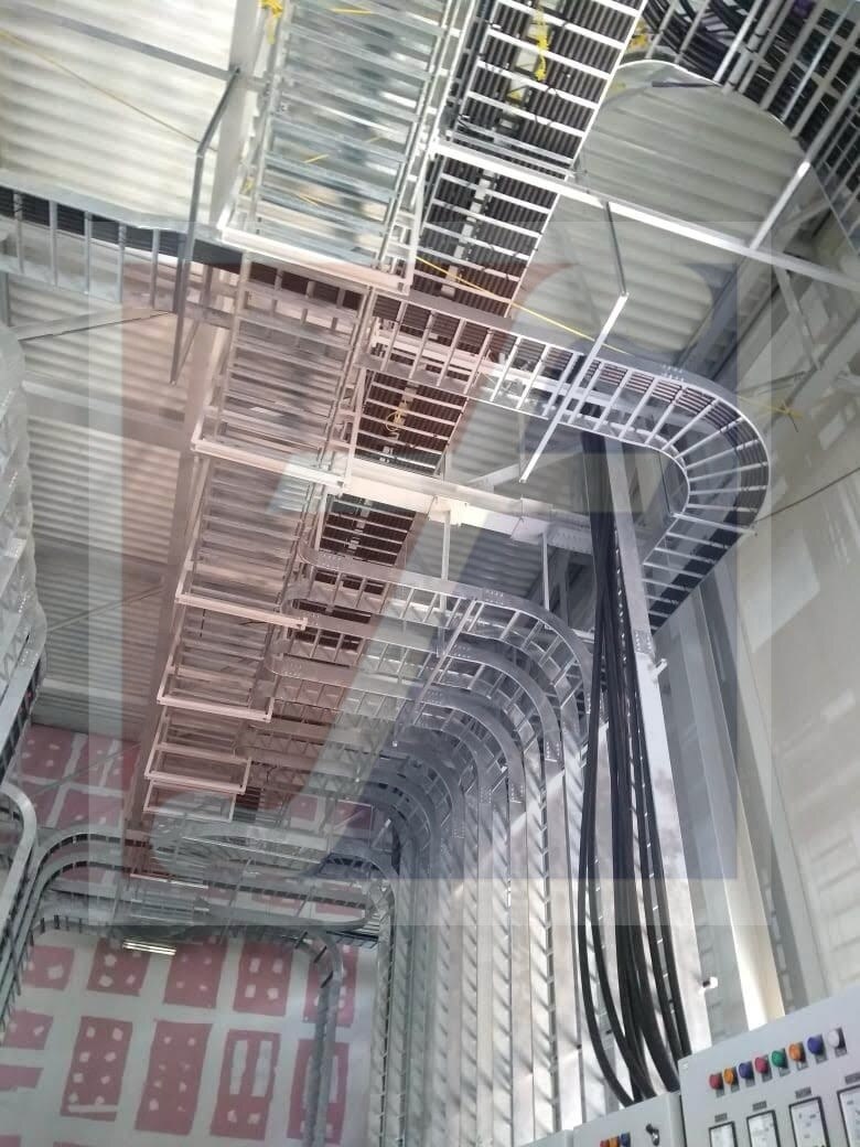
The inside throat controls the route, not the outside rail or nominal tray width. If its inside radius is too tight, a cable can exceed its minimum bending radius before it reaches the branch. The outer-radius path is longer than the inner path, so measuring the outside rail gives a false sense of clearance.
Left-hand, right-hand, and straight-through tees are not interchangeable. Their tee branch orientation changes the cable’s bend direction, separation, and approach to connected equipment. Ladder tray tee-bend problems also begin with inaccurate site measurements that produce the wrong branch depth, width, side-rail height, or steelwork clearance.
| Cable type | Junction check | Failure risk |
|---|---|---|
| Power | Maintain phase separation and clearance through the throat | Jacket damage, excessive pulling tension, or overheating |
| Control | Keep control circuits separated from power cables | Electrical interference and crushed insulation |
| Instrumentation | Preserve pair spacing and the specified bend radius | Signal error or damaged shielding |
| Fibre-optic | Respect the manufacturer’s minimum radius and protect the cable from loading | Attenuation or fibre breakage |
Compare the tightest measured radius with the cable datasheet’s minimum cable bending radius, pulling-tension limit, and sidewall-pressure limit. A cable that can be placed by hand can still fail during pulling. Mismatched tray systems, branch depth, rail profile, or field dimensions are design and ordering errors unless inspection proves distortion, burrs, or another manufacturing defect.
Dimensional Checks Separate a Defective Tee From a Bad Fit
A tee is defective when its measured geometry fails the approved drawing or cannot match the specified straight tray without force. Use this tee bend dimensional inspection before installation, not after cables conceal the throat.
1. Measure tray width, side-rail height, flange profile, material thickness, bend angle, inside radius, and rung spacing. Compare each result with the approved drawing and the adjoining straight tray. An incorrect angle, undersized throat, uneven rungs, side-rail distortion, or a step between sections indicates a dimensional defect.
2. Check the joining-plate pattern, splice-plate position, and every bolt hole against the straight section. A bolt-hole mismatch, forced assembly, twisted rail, or distorted flange points to wrong manufacture or weld distortion; do not enlarge holes to make the joint fit.
3. Inspect all cable-contact surfaces by hand and sight. Reject burrs, sharp edges, protruding welds, weld distortion, and coating runs that reduce the usable radius or create snag points. Measure the actual inside radius rather than accepting the catalogue value.
4. Treat a fit problem as installation-related when both parts meet their drawings but the crew mixed systems with identical nominal widths, selected the wrong handed fitting, cut away the designed overlap, or placed a splice where the geometry cannot align. Recheck the splice-plate alignment before blaming the tee.
5. Record photographs of each defect, measured dimensions, batch identification, and the exact adjoining tray part numbers. Include the drawing revision and mark whether the failure occurred before assembly or after field cutting, drilling, or repositioning.
Cable Weight, Fill, and Supports Turn a Correct Tee Into a Failure
A tee cannot inherit the straight-tray load rating automatically. Its tee fitting load rating depends on the actual radius, branch geometry, support arrangement, and span tested by the fitting manufacturer; an unsupported tee can fail under a load that a straight section carries safely.
Calculate the combined cable area with a cable tray fill calculation, then apply the project’s tray-fill limit, segregation requirements, cable grouping rules, and heat-dissipation clearances. A branch creates no extra fill allowance. Crowding at the throat can overload one rail and restrict cooling even when both straight runs appear lightly filled.
Check these conditions before installation:
- Confirm the manufacturer’s tested load table for the actual tee radius, span, support arrangement, and cable arrangement.
- Provide branch-arm support where the branch acts as a cantilever; wide support spacing, long unsupported arms, excessive fill, and concentrated throat loading cause sag and misalignment.
- Keep cables from loading one rail during the turn. Eccentric loading twists the fitting, opens splice joints, and shifts adjoining trays.
- Treat splice joints as connections, not structural supports, and keep splice locations away from support points.
- Check the cable datasheet before pulling. Sidewall pressure and longitudinal tension at the tee can exceed cable limits even when the cable can be placed by hand.
Use the pulling radius and limits specified for the cable, not only the fitting’s physical clearance. A cable route that survives placement can still fail during pulling.
Material, Finish, Expansion, and Bonding Decide Whether the Tee Survives
A tee survives its route only when the material and finish match the exposure. Do not assume that a galvanized cable tray is suitable because it looks protected; require the project coating specification, including coating type, thickness, repair method for cut edges, and temperature limits.
| Material | Exposure decision | Main failure to prevent |
|---|---|---|
| Galvanized steel | Outdoor routes and coastal corrosion protection when the specified zinc system suits the atmosphere | Poor galvanizing, damaged cuts, and exposed burrs rusting or abrading cable jackets |
| Painted steel | Chemical areas only when the paint system is named and compatible with the chemicals and temperature | Scratched or cut coating exposing steel |
| Stainless steel | Washdown and chemical zones when the specified grade and fasteners are compatible | Crevice or galvanic corrosion at joints |
| Aluminium | Routes where low mass or temperature performance suits the design | Dissimilar-metal corrosion against steel supports or fasteners |
Deburr every field cut and restore its specified corrosion protection. A sharp edge, coating run, protruding bolt, or weld distortion can reduce the usable throat and cut a jacket as cables move.
On long metallic routes, locate each thermal expansion joint from the route design; do not lock a tee between long runs and add an arbitrary gap. Expansion forces otherwise load splice plates and supports. Coordinate the thermal expansion joint with support locations and cable tray bonding continuity.
Mechanical bolts do not prove electrical continuity. Paint, oxidation, galvanizing, incompatible metals, or nonconductive washers can interrupt bonding, so specify and test the bonding path.
Fixotech Engineering Systems Pvt Ltd: Manufacturer of Cable Management Systems becomes useful when the purchase schedule states route-specific material, finish, radius, load, supports, expansion joints, and bonding—not just nominal tray width.
The Acceptance File Should Prove the Tee Is Fit for the Route
Before release, build a cable tray acceptance checklist around the approved plan and elevation drawings, not the catalogue image. The file must identify tee handedness, bend-radius drawing, tray width and height, material grade, thickness, finish specification, dimensional tolerances, load table, allowable support span, joining hardware, and splice detail.
1. At receiving inspection, compare the tee with the approved drawings and adjoining tray. Record the manufacturer inspection record, batch number, measured dimensions, and photographs. Reject the part for wrong dimensions, distortion, burrs, sharp edges, coating runs, weld defects, or splice holes that do not align.
2. Confirm the governing project documents before citing IEC 61537 or NEMA VE 1. Check either standard only when the project specification or governing jurisdiction adopts it; neither is an automatic compliance claim. Confirm the fitting’s tested load rating for its radius, support arrangement, and span rather than applying a straight-tray rating.
3. Before cable placement, check level and alignment, independent branch support, bolt torque, deburred field cuts, cable clearance, throat fill, and splice position. Keep splices away from supports. Correct poor support, wrong orientation, misplaced splices, or excessive fill; a branch without independent support can twist the tee and open its joints.
4. After installation, inspect cable jacket condition and perform bonding-continuity testing across joints, coatings, and expansion provisions. Revise the design when radius, cable separation, loading, or thermal-movement provisions are inadequate. A sound acceptance file proves whether the failure belongs to the part, the installation, or the route design.
Frequently asked questions
How can tee geometry damage cables in an industrial route?
A tight inside throat or radius can force cables below their specified minimum bending radius before they reach the branch. The outer rail can appear clear while the inner path remains damaging.
How do you distinguish a defective tee from a bad fit?
Measure the tee’s inside throat, bend radius, width, height, branch alignment, and support locations against the approved drawing and cable requirements. A dimensional mismatch identifies a bad fit; a failure to match the drawing indicates a defective tee.
How do cable weight, fill, and supports cause tee failures?
Excessive fill and cable weight increase loading at the branch, while missing or widely spaced supports let cables sag, twist, or overload the fitting. Check the combined load and support arrangement rather than the tee alone.
Which material, finish, expansion, and bonding checks matter?
Confirm the specified material and coating, inspect the finish for damage, provide movement allowances at expansion points, and verify electrical bonding across joints where the route requires continuity.
What belongs in a tee bend acceptance file?
Keep the approved drawing, measured dimensions, material and finish records, load and fill calculations, support layout, expansion details, bonding checks, inspection results, and corrective-action records.