Choosing a ladder tray by width or appearance can leave a facility with overloaded supports, poor cable separation, corrosion damage, or inadequate protection at exposed routes. You will be able to match tray construction to facility use, calculate capacity from the cable schedule, and specify when ladder tray, covered tray, conduit, or another pathway is the safer choice.
Key takeaways
- Use ladder tray for long, accessible routes carrying substantial power cables.
- Size tray from cable diameter, fill allowance, bend space, and future capacity.
- Separate power, telecommunications, control, and instrumentation cables by route or divider.
- Choose coated, stainless steel, or enclosed containment for corrosive or exposed locations.
Where ladder tray fits across Chennai facilities
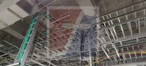
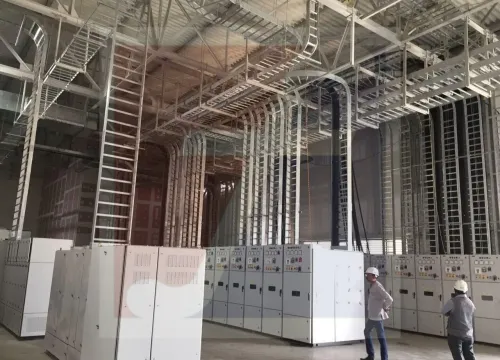
Long, accessible routes carrying substantial power are the strongest ladder cable tray applications in Chennai. Manufacturing plants, substations, data centres, commercial buildings, infrastructure projects, and utility rooms use it for runs between incoming feeders, transformers, switchgear, motor-control centres, generators, UPS equipment, and final panels.
| Facility route | Good ladder-tray candidates | Check before selecting |
|---|---|---|
| Manufacturing plant | Motor feeders, process-power cables, control and instrumentation routes | Separate power from sensitive circuits; allow maintenance access |
| Substation or utility room | Transformer-to-switchgear runs and incoming or outgoing feeders | Verify fault-force restraint, bonding, span, and cable cleats |
| Data centre | Generator, UPS, switchboard, and mechanical-services power routes | Keep telecommunications and fibre routes separated from power |
| Commercial or infrastructure project | Plant-room feeders, risers, and long service corridors | Confirm fire-survival requirements for emergency circuits |
Open rungs provide ventilation and let operators inspect or replace cables without pulling them through a closed enclosure. They suit routes with long spans, elevation changes, and direction changes, but the complete system must match the declared load and span tables; sheet thickness alone proves nothing.
For outdoor ladder cable tray applications in Chennai, specify the corrosion category and finish against humidity, monsoon wetting, industrial contaminants, and coastal salt. Hot-dip galvanized steel, aluminium, or stainless steel may fit different exposures. Do not treat ordinary steel tray as fire-rated: emergency feeders and life-safety circuits need a tested fire-survival cable-and-support arrangement.
How ladder tray carries power distribution routes
Start at the incoming service or generator and keep the route continuous to the final equipment, using ladder tray for power distribution wherever cables need ventilation, inspection, and later replacement. Plan tray elevation, direction changes, and transitions before fixing supports; do not force a cable around a corner tighter than its manufacturer’s minimum bending radius.
Use the route in this order:
- Incoming feeders: carry service cables to the main switchboard, with entry plates, edge protection, and cleats sized for prospective short-circuit forces.
- Transformer runs: support primary and secondary cables without unsupported drops, and check heat dissipation around closely grouped circuits.
- Switchgear to motor-control-centre feeders: maintain the cable schedule’s phase grouping, spacing, and separation from instrumentation or communication routes.
- Generator and UPS routes: provide independent paths where redundancy or source segregation is required, including clear identification at every transition.
- Final equipment connections: use approved bends, risers, glands, and flexible sections so tray movement does not load terminals or cable entries.
Single-core AC cables need special attention. Arrange conductors as balanced circuits or trefoil groups; a ferromagnetic steel arrangement that separates or encloses individual conductors can increase impedance and heating. Check the cable manufacturer’s installation limits and IEC 60287 calculations.
Do not infer ampacity from tray width alone. Apply derating for grouping, ambient temperature, solar exposure, orientation, and cable spacing, then select supports from the complete system’s span/load tables, including concentrated loads and splice locations. Ordinary steel ladder tray is not fire-rated; emergency feeders require a tested fire-survival cable-and-support arrangement.
How to route telecommunications, control, and instrumentation cables
1. Assign separate routes before installing ladder tray for telecommunications. Keep copper data, optical-fibre, control, instrumentation, and power cables in dedicated trays or separated compartments. If a power route must cross a communications route, cross at close to 90 degrees and maintain the project’s specified clearance.
2. Check every entry, exit, tee, and transition to equipment. Select radius bends, drop-outs, and edge protection that preserve each cable’s stated minimum bend radius. Do not pull fibre or copper data cables around a sharp rung or force a control cable into a crowded corner; crushing and excessive tension can create intermittent faults.
3. Control electromagnetic interference by keeping noisy circuits away from analogue instrumentation, communication copper, and sensitive control cables. Keep cable spacing consistent, avoid parallel runs beside motors and variable-frequency drives, and use screened cables with shields terminated according to the equipment manufacturer’s instructions.
4. Bond metallic tray sections across splice plates, expansion joints, painted surfaces, and accessories. Install bonding jumpers where the designed continuity path requires them, then test continuity; touching steel sections do not prove a low-impedance bond.
Use clamps or cleats at entries and exits where movement or fault forces could damage cables, and preserve separation again at the equipment connection.
How to size ladder tray from the cable schedule
Size the tray from the cable schedule, not from a preferred width. Record each cable’s outer diameter, quantity, weight per metre, minimum bending radius, voltage class, and grouping; then add the planned spare capacity without exceeding the manufacturer’s fill basis.
For ladder cable tray industrial use, use the complete system’s tested load table at the actual support span. Sheet thickness alone proves little. Check concentrated loads, splice positions, cantilevered ends, allowable deflection, and the added wind or seismic load where the route requires it.
Request these schedule inputs before approving the tray:
- Cable list: type, outer diameter, metre weight, quantity, bending radius, and separation class.
- Route geometry: straight-run length, horizontal and vertical bends, elevation changes, support span, and unsupported ends.
- Mechanical load: total cable weight, spare allowance, accessories, and any point load from cleats or clamps.
- Fault duty: prospective short-circuit current, fault duration, cleat spacing, and the tray or support forces transferred during a fault.
- Growth: reserved width or loading for identified future circuits, not an arbitrary percentage.
| Input | Tray decision | Evidence to request |
|---|---|---|
| Cable diameter and count | Width, rung spacing, and bend accessories | Outer-diameter schedule and fill calculation |
| Cable weight | Load class and support spacing | Declared working load at the stated span |
| Span and direction changes | Rail depth, splice locations, and deflection limit | Tested or declared load-span table |
| Fault current | Cleat, clamp, and support capacity | Short-circuit force calculation |
| Outdoor exposure and expansion | Material, finish, and expansion joints | IEC 61537 compliance, corrosion specification, and joint details |
When Chennai exposure calls for another containment method
Select the containment method by exposure, access, and cable vulnerability—not by tray width alone. For a cable trays manufacturer, ladder tray for applications in Chennai must account for humidity, monsoon wetting, industrial contaminants, ultraviolet exposure, and coastal salt.
- Choose open ladder tray for large power bundles in factories, substations, utility rooms, data-centre support areas, and infrastructure routes where inspection, ventilation, and future additions matter.
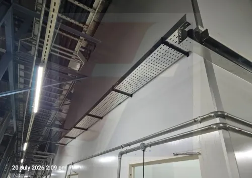
- Choose perforated tray for smaller control, instrumentation, telecommunications, or mixed services needing a more continuous support surface and easier underside protection.
- Add a cover where falling objects, wash-down, sunlight, rodents, or unauthorized access threaten exposed cables. A cover does not replace correct cable spacing or ampacity calculations.
- Choose conduit for short exposed drops, individual equipment connections, severe mechanical-risk zones, or routes needing enclosed protection. It increases pulling effort and complicates later cable replacement.
- Choose enclosed raceway for clean, protected communication or control routes inside buildings where appearance, access control, and segregation matter more than open ventilation.
Require the supplier to state IEC 61537 compliance, material grade, documented corrosion category, coating standard, side-rail depth, rung spacing, allowable working load at the stated span, deflection limit, splice and expansion-joint details, bonding provisions, and inspection records.
Ordinary pre-galvanized sheet is not an automatic outdoor solution; compare hot-dip galvanized steel, aluminum, and stainless steel against the site exposure.
When reviewing Fixotech Engineering Systems Pvt Ltd: Manufacturer of Cable Management Systems, ask for these values on the quotation rather than accepting “heavy duty ladder tray” as a specification.
Related products
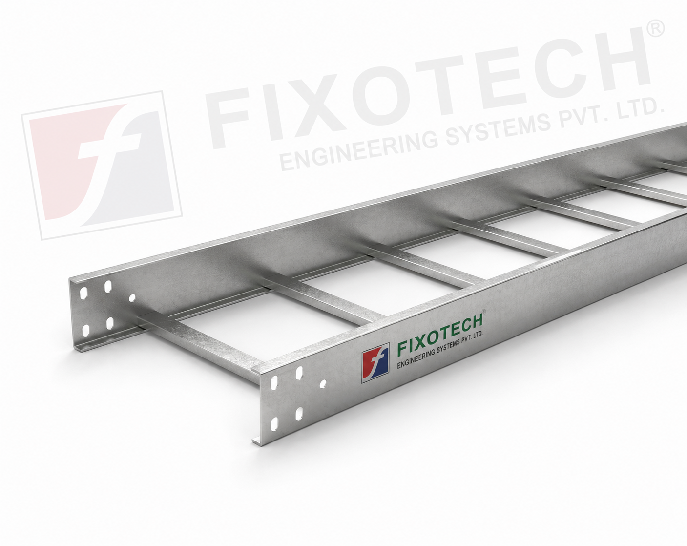 | LADDER CABLE TRAY Other common name in Cable tray industry is ladder tray. Simple design consisting of side rails with rungs connected. View product → |
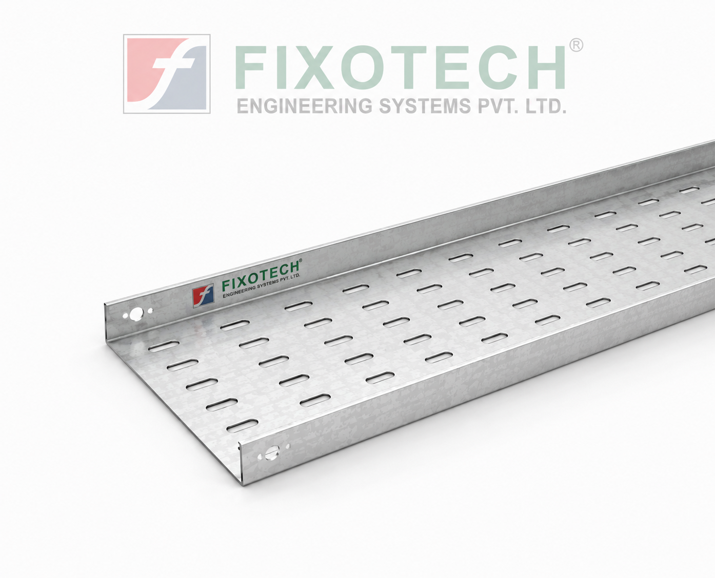 | PERFORATED CABLE TRAY Perforated Tray In electrical systems, a perforated cable trayeither with or without coversis a typical part used to support and arrange cables. View product → |
Frequently asked questions
Where do ladder trays fit across Chennai facilities?
Ladder trays suit long, accessible cable routes in manufacturing plants, substations, data centres, commercial buildings, infrastructure projects, and utility rooms.
How should you size ladder tray from a cable schedule?
Add the outside diameters of scheduled cables, apply the project fill limit, allow bend space at changes of direction, and reserve capacity for future cables.
Can ladder tray carry telecommunications, control, and instrumentation cables?
Yes, when you maintain the required separation from power cables, use suitable dividers or dedicated trays, and protect sensitive circuits from interference and physical damage.
When should you choose another cable containment method?
Use enclosed trunking, conduit, or a corrosion-resistant system when cables face dust, water, chemicals, impact, unauthorised access, or harsh outdoor exposure.
Related products
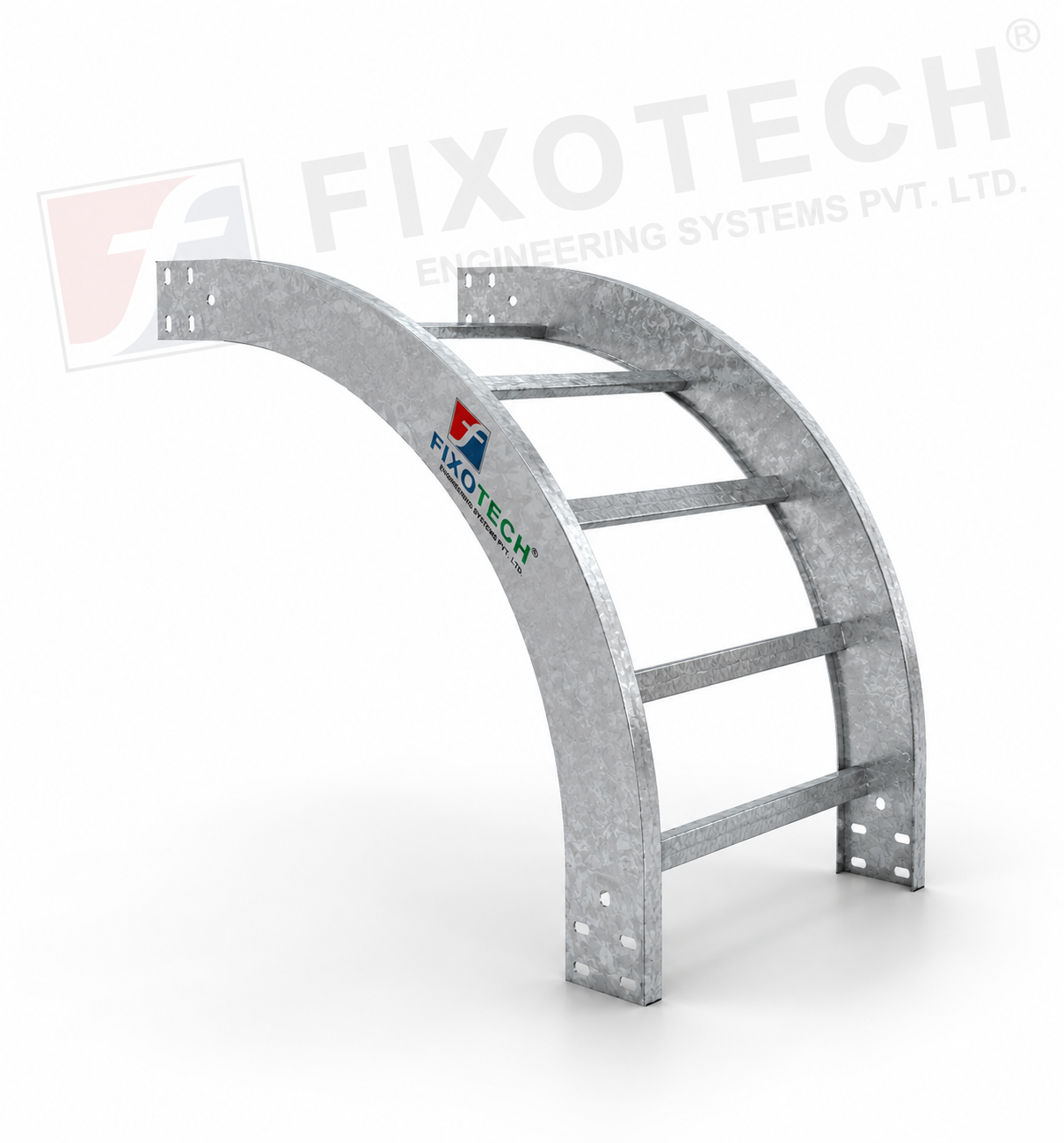 | LADDER CABLE TRAY A particular kind of cable tray called a vertical bent ladder cable tray is made to make it easier to route wires in vertical cable management... View product → |
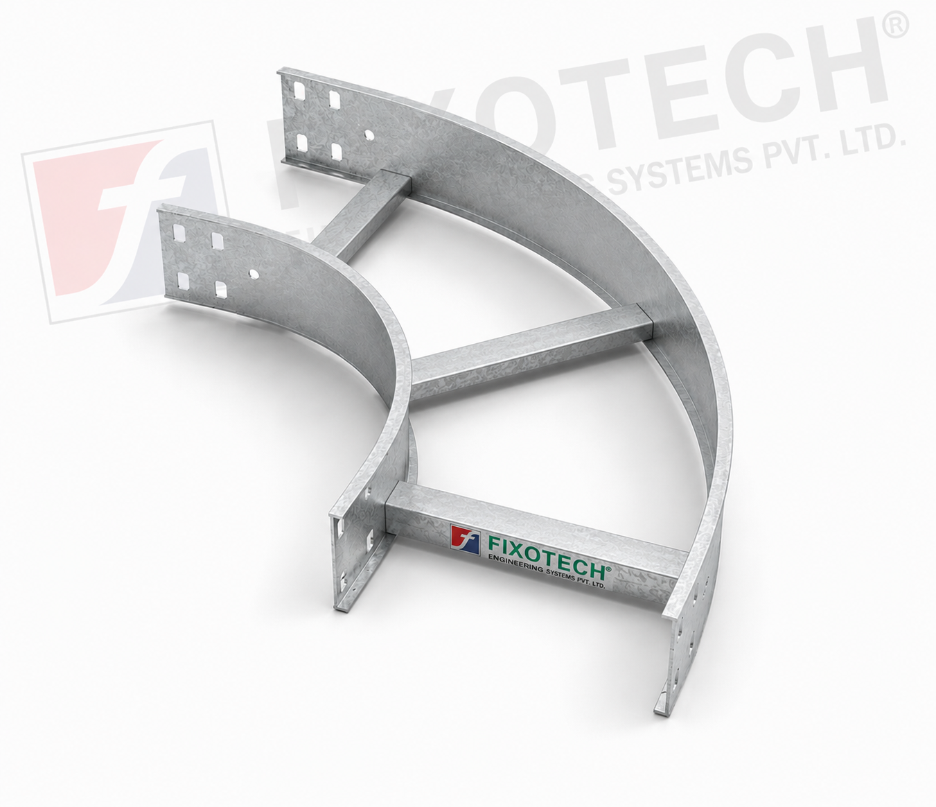 | LADDER CABLE TRAY The purpose of a horizontal ladder bend cable tray is to make it easier for cables to be routed around bends or corners in horizontal cable... View product → |
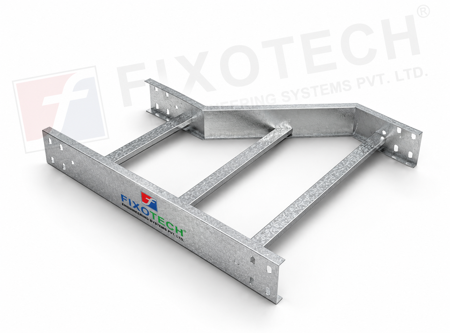 | LADDER CABLE TRAY REDUCER One particular kind of cable tray part made to make switching between cable trays of various widths or diameters easier is the reducer ladder cable... |
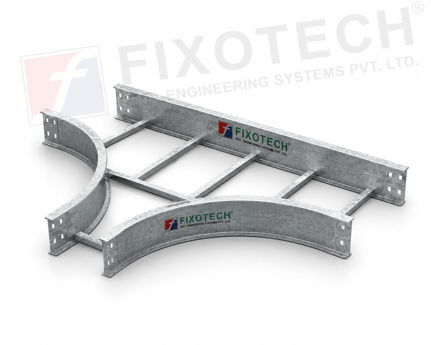 | LADDER CABLE TRAY One particular kind of cable tray made to make it easier to route cables at T-junctions in horizontal cable management systems is the ladder tee bend... View product → |