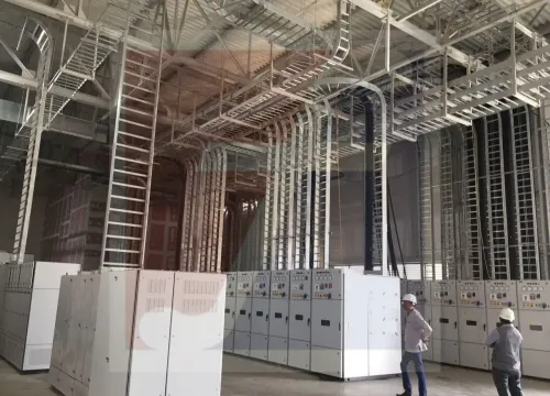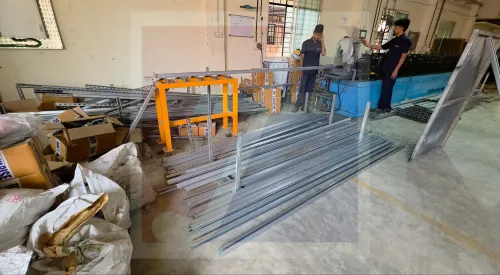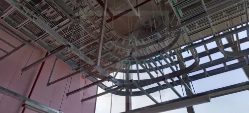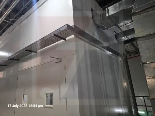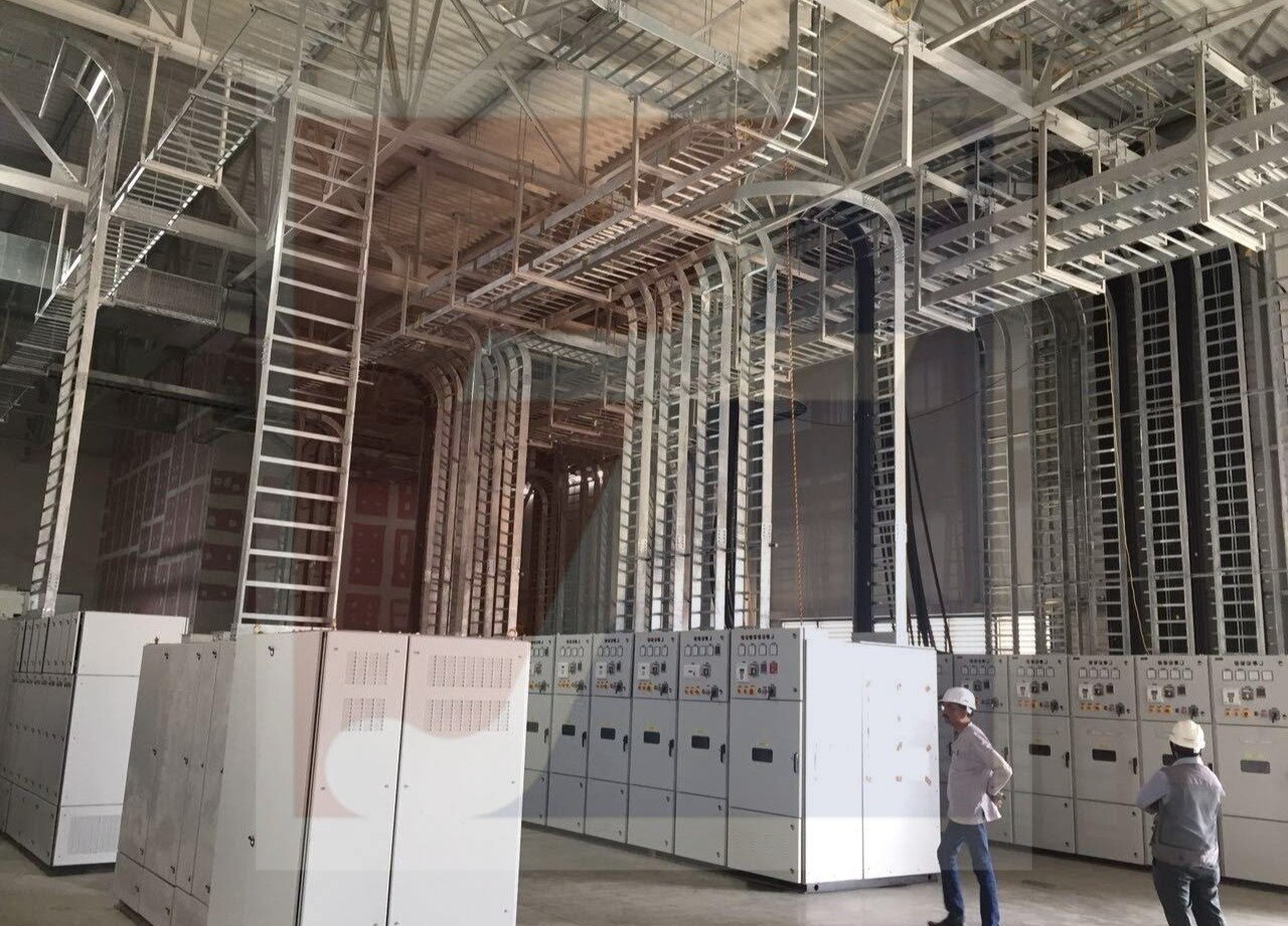
A horizontal bend turns a tray route at a plan-view corner, but a 90-degree label does not define the radius, load, support arrangement or cable suitability. By the end, you will be able to measure the route, select a bend that matches the cables and tray system, and write a purchase specification that avoids installation problems.
Key takeaways
- A 90° bend changes direction without raising or lowering the tray route.
- Match bend radius to the largest cable’s minimum bending radius.
- Measure tray width, height, route angle, and available clearance before ordering.
- Specify tray type, material, finish, radius, angle, and connection hardware.
How a horizontal bend changes the tray route
A horizontal bend turns the tray in plan view; it does not raise or lower the route. A 90° bend sends the straight section onto a perpendicular alignment, while a 45° bend creates a diagonal change that needs more length before the route reaches its final direction.
The bend angle sets the change in direction. The inside radius sets the curve followed by the cable, and the tray width determines the outer edge: outside radius equals inside radius plus tray width. Both straight sections must align tangentially with the bend ends, or the cable will meet a step, twist, or sharp transition.
This geometry is the basis of horizontal bend cable routing.
Choose the radius from the cable manufacturer’s minimum installation bend radius, not from tray width. Power, control, instrumentation, and fibre-optic cables can require different radii, so a mixed route must accommodate the largest applicable requirement. A larger radius lowers sidewall pressure and eases pulling, but consumes more floor or ceiling space.
A compact bend suits a tight route only when the cable radius and clearance permit it. If the required turn cannot fit a standard 90° bend, use a larger-radius bend, a fabricated offset, or multiple angle pieces.
Confirm the straight lengths on both sides before ordering; a bend without enough adjoining tray can place a splice or support at the curve. Check bend supports separately because straight-tray load ratings do not automatically apply to the curved section.
How to choose the radius for each cable type
Choose a ladder cable tray horizontal bend whose cable path radius meets or exceeds the cable manufacturer’s minimum installation bend radius. Do not select it from tray width alone, and do not confuse a horizontal bend with an inside or outside vertical bend.
| Cable type | What to check | Selection consequence |
|---|---|---|
| Power cable | Minimum installation radius, pulling tension and sidewall pressure | Use the largest required radius among the power cables |
| Control cable | Installation and final bend-radius limits | Do not assume its smaller diameter permits the same bend as power cable |
| Instrumentation cable | Supplier’s minimum radius and separation requirements | Check the most restrictive cable in the instrument group |
| Fibre-optic cable | Minimum installation and permanent radius | Protect against tight bends during pulling and dressing |
Use the cable manufacturer’s installation radius, not only the permanent installed radius. If the cable datasheet states a multiple of cable diameter, calculate that value for the actual cable size. For a mixed route, select the bend for the cable requiring the greatest radius, or separate incompatible cables into different routes.
Confirm whether the tray supplier quotes inside radius, centreline radius or radius to the cable-support surface. Compare like with like: the innermost cable path must still meet its specified radius. A 90-degree bend is not automatically suitable for pulling; calculate pulling tension and sidewall pressure for long or heavily populated routes.
- Request cable datasheets and the pulling calculation.
- Mark the largest required radius on the tray layout.
- Confirm the bend, radius plates, splice plates and supports are tested as one IEC 61537-based system.
What to measure before ordering a bend
Measure the existing route and the cable envelope before requesting a ladder tray bend in Chennai. A “90-degree bend” is incomplete: the supplier also needs the tray section, radius, load, supports, finish and connection details.
Record these items from the approved layout and site survey:
- Tray width and side-rail height, measured on the straight section.
- Turning angle and inside radius, plus the resulting outside radius and tangent lengths.
- Straight-tray lengths available before and after the corner.
- Clearance from walls, columns, pipes, equipment and access walkways. Check the outside radius, not only the tray centreline.
- Cable quantity, largest cable diameter, minimum installation bend radius, pulling tension and sidewall-pressure limit.
- Support type, support-span requirement, bracket locations and the distance from each support to the bend or splice.
- Design load, including cable weight and future capacity.
- Splice-plate pattern, fastener type, rung spacing, material, coating and electrical-continuity requirement.
| Check | Measure or confirm | Why it matters |
|---|---|---|
| 90-degree corner | Inside radius, outside radius and tangent lengths | Prevents clashes and short straight sections |
| Tight plantroom route | Obstruction clearance and access width | Avoids an un-installable fitting |
| Mixed cables | Largest required cable radius | A tray radius alone does not protect every cable |
| Unsupported corner | Support position and span | Preserves load rating and limits deflection |
For a cable route exposed to Chennai’s coastal air, wash-down or chemicals, state the environment before selecting material and finish. Ask for the bend as part of the same tested tray system; mixing radius plates, rails or supports from different systems can invalidate the published performance.
How tray types and bend components affect installation
Ladder, perforated, raceway and field-fabricated corners solve different installation problems. Choose the tray form around ventilation, protection, access, loading and the amount of site adjustment required.
| Option | Practical advantage | Trade-off at a horizontal bend |
|---|---|---|
| Ladder tray | Open rungs improve ventilation, inspection and cable access; fittings are usually lighter | Small cables can sag between rungs, and exposed cables need careful cleating and edge protection |
| Perforated tray | Continuous base supports smaller control and instrumentation cables and limits cable droop | More metal increases weight and restricts ventilation; debris and water can collect in the perforations |
| Raceway | Enclosed sides and cover protect cables from impact, dust and wash-down | Cable pulling, heat dissipation and later additions become harder; the bend must match the cover and base |
| Field-fabricated corner | Lets installers resolve an obstruction or unusual angle without waiting for a special fitting | Cutting can reduce strength, create sharp edges and interrupt bonding unless the joint is properly reinforced |
For reliable horizontal bend cable routing, align the bend’s tray width, side-rail height, inside radius and flange pattern with both straight sections. Staggered widths create a cable snag point; mismatched radii force cables against the side rail.
Use the manufacturer’s splice plates, fasteners and support arrangement, then remove burrs and fit edge protection where a cable crosses a cut end.
- Keep the tray centreline continuous through the corner.
- Match cover dimensions on raceway bends.
- Bond metallic sections across every joint and verify electrical continuity.
- Support the bend near its ends and at the spacing stated for the selected load and span.
How to specify a compatible bend from a manufacturer
A search for cable management systems manufacturer chennai horizontal bend is only a starting point. Give the cable management systems manufacturer a complete compatibility brief before accepting a quotation, because a visually similar bend can have different load capacity, splice arrangements and electrical-continuity performance.
1. Identify the existing tray by type, material, finish, width, side-rail height, rung or perforation pattern, and straight-section model. Send photographs, measurements and the manufacturer’s drawing or part number.
2. State the required angle, inside radius, outside radius, tray width, straight lengths and available clearance. Confirm that the bend’s radius plates, side rails, splice plates, fasteners and support locations match the existing system.
3. Request the declared test basis: IEC 61537, NEMA VE 1, or the project specification. Ask for load-versus-span data, allowable deflection, support spacing, splice requirements and electrical-continuity provisions. NEMA VE 2 helps compare installation practice but does not replace the project’s electrical code.
4. Provide the cable schedule, including power, control, instrumentation and fibre-optic cables. The selected radius must meet the cable supplier’s minimum installation radius, pulling-tension limit and sidewall-pressure limit; the tray’s nominal radius alone is not sufficient.
5. Describe the site as indoor, outdoor, coastal, chemically exposed or wash-down, then specify the required material and finish. Fixotech Engineering Systems Pvt Ltd: Manufacturer of Cable Management Systems can use this information to distinguish a standard component from a corrosion-resistant or customized bend.
6. Obtain a drawing showing the complete assembled corner, part numbers and installation instructions before ordering. Do not mix an unverified bend with straight sections from another system.
Frequently asked questions
How does a horizontal bend change a cable tray route?
It changes the route in plan view. A 90° bend creates a perpendicular alignment, while a 45° bend creates a diagonal transition.
How do you choose the radius for each cable type?
Use the cable manufacturer’s stated minimum bending radius and select a bend that preserves that limit during installation.
What should you measure before ordering a horizontal bend?
Measure tray width, side-rail height, route angle, centre-line radius, straight-run positions, support spacing, and surrounding clearance.
Which details should you specify to a cable tray manufacturer?
State the tray type, width, side-rail height, material, finish, angle, centre-line radius, load requirement, and connection hardware.