A perforated cable tray order can fail before production when the buyer supplies only a width, a quantity, and a delivery date. By the end, you will know what information to submit, how to turn a route and cable schedule into a bill of materials, how to compare quotations, and what to verify before installation.
Key takeaways
- Send route drawings, cable schedules, delivery details, and site access constraints.
- Size tray width from cable area, separation rules, spare capacity, and bend space.
- Confirm material, finish, load requirements, dimensions, and governing standard in writing.
- Approve fabrication drawings before production and inspect quantities, finish, and accessories on delivery.
Start with the route, cable schedule, and ordering checklist
A useful quotation starts with the route, not a guessed tray width. Send the route drawing or marked-up plan, cable schedule, and site delivery location so the manufacturer can price straight runs, changes in direction, supports, and access constraints. This is the information to provide to a perforated cable trays manufacturer for ordering process review:
1. State tray type, overall width, side-rail height, straight-section length, sheet thickness, material grade, perforation pattern, and finish.
2. Attach the cable schedule with each cable’s outside diameter, quantity, separation requirement, circuit grouping, total load, and spare capacity allowance.
3. Give route dimensions, elevation changes, bend radii, support span, installation environment, and the required load rating. Without the support span, two quotations that show the same width are not technically comparable.
4. Count every fitting: horizontal and vertical bends, tees, crosses, reducers, risers, drops, covers, splice plates, bonding jumpers, and support hardware.
5. Identify the governing requirement, such as NEMA VE 1 with its edition and load basis, and state whether NEMA VE 2 installation guidance applies.
6. Request the manufacturer’s drawing, bill of materials, delivery date, coating description, and inspection documents before placing the perforated cable tray order.
Ask who controls the design, punching, forming, and finishing. If hot-dip galvanizing follows fabrication, confirm that vent and drain openings are shown on the drawing; their location affects both galvanizing safety and the approved geometry.
Turn cable data into tray dimensions and a complete bill of materials
Set tray width from the cable schedule, not from the route drawing alone. Add the outside diameter of every cable sharing a route, the specified separation between circuits, and the clearance needed for dressing and termination. Add the project’s future-capacity allowance, then select the next available internal width.
Side-rail height must contain the cable stack without obstructing bend radius or cover fit. Confirm the cable manufacturer’s minimum bending radius at every riser, drop, and turn; a tray that fits on the straight route can fail at a vertical bend.
Calculate loading in kilograms per metre from cable weights, then add the tray and cover weights. Compare that total with the manufacturer’s load rating at the stated support span, not at an unspecified span. Omitting span makes two apparently similar quotations impossible to compare.
Convert the route centreline into straight sections and fittings. Count each change in direction and elevation, then identify the required geometry:
- Straight tray sections by route length and standard section length
- Horizontal and vertical bends at route changes
- Tees, crosses, reducers, risers, and drops at branch points
- Covers where protection or segregation requires them
- Splice plates, fasteners, and bonding jumpers where continuity requires them
- Supports and clamps at the approved spacing
Your perforated cable tray order should show width, side-rail height, thickness, perforation pattern, material, finish, support span, load rating, and delivery quantity for every line item. Ask for a dimensioned fitting schedule before approving the bill of materials.
Choose the tray system, material, finish, and governing standard
Perforated tray suits routes needing ventilation, cable-tie access, and moderate protection from mechanical impact. Choose solid-bottom tray where small objects, dripping liquid, or frequent washdown can reach the cables; choose ladder tray when high airflow, heavy cables, or long spans dominate. Load capacity belongs to the complete system, not sheet thickness alone.
| Construction choice | What it means | When it applies |
|---|---|---|
| Pre-galvanized steel | Sheet is coated before punching and forming; cut edges remain a corrosion consideration | Dry indoor routes with controlled exposure |
| Hot-dip galvanized after fabrication | Formed tray and fittings receive a zinc coating after fabrication, including exposed edges | Outdoor, humid, or corrosive areas |
| Stainless steel | Corrosion-resistant alloy throughout the tray and fittings | Chemical, coastal, food-processing, or washdown environments |
Give the perforated cable tray supplier a single construction brief containing:
- Tray type, width, side-rail height, straight length, perforation pattern, thickness, material grade, cover, fittings, splice plates, and support span
- Required load rating, including concentrated loads, plus the supplier’s load/span table for the exact series
- Finish sequence: ask whether punching and forming occur before galvanizing, as required by the exposure and corrosion-control plan
Specify IEC 61537 for system performance, or NEMA VE 1 with its edition, load basis, and installation assumptions. NEMA VE 2 is an installation guideline, not the product standard. Ask how joints, bonding, covers, and supports satisfy the selected standard.
During the perforated tray manufacturing process, Fixotech Engineering Systems Pvt Ltd: Manufacturer of Cable Management Systems should identify who controls design changes, fabrication, finishing, and coating documentation.
Compare the quotation, approve the drawing, and release production
Do not compare prices until every quotation uses the same technical basis. Your perforated cable trays manufacturer for ordering process checklist should identify tray width, side-rail height, straight-section length, thickness, material grade, finish, perforation pattern, covers, fittings, splice hardware, load rating, support span, quantities, and delivery location.
| Check before comparison | Technically complete quotation | Incomplete quotation |
|---|---|---|
| Standard | NEMA VE 1 edition or IEC 61537 basis, with load class and installation assumptions | “NEMA compliant” |
| Construction | Material, thickness, punching, forming, and finish sequence | “Galvanized tray” |
| System scope | Straights, bends, tees, reducers, covers, supports, joints, and bonding provisions | Tray price only |
| Responsibility | Identified designer, fabricator, finisher, and document issuer | Unnamed source |
A perforated cable tray supplier may be a manufacturer, stockist, or assembler. Confirm who controls design changes, performs punching and forming, applies the finish, and issues dimensional and coating records; this determines who supports traceability and warranty claims.
Review the manufacturer’s drawing against the route, support span, fitting geometry, cable entry points, and splice locations. For post-fabrication hot-dip galvanizing, require correctly located vent and drain openings in enclosed or partially enclosed sections. These openings enable safe galvanizing and can change the approved drawing.
Approve the drawing in writing, including revision number, quantities, finish, and accessories. Then issue the purchase order with the approved drawing attached. Production should start only after the manufacturer acknowledges that revision; later changes can cause rework, delays, and mismatched fittings.
Inspect, dispatch, and hand over the installed tray system
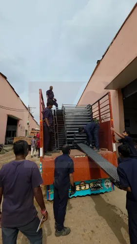
Check the delivery against the approved drawing and packing list before unloading the perforated cable tray order. Count straight lengths and every fitting, then inspect perforations, side-rail height, thickness, finish, covers, splice plates, fasteners, and bonding jumpers for damage or substitution.
1. Match each bundle label to the purchase order, delivery note, and bill of materials. Missing tees, reducers, risers, or support hardware can stop installation even when all straight tray has arrived.
2. Measure samples for width, height, straight-section length, and sheet thickness. Check that the perforation pattern, material grade, coating, and fitting geometry match the approved submittal.
3. Photograph dents, bent flanges, damaged coating, corrosion, wet packaging, and missing parts before signing the delivery note. Record bundle numbers and notify the perforated cable tray supplier immediately.
4. Confirm the supplier has provided the exact tray-series load/span table, support details, splice hardware instructions, and bonding provisions. IEC 61537 treats the tray and its joints, covers, supports, and electrical continuity as a system, not as unrelated sheet-metal pieces.
5. Assemble the installation handover file with the approved layout and fitting drawings, final bill of materials, as-built route drawings, delivery notes, material certificates, coating or galvanizing records, installation instructions, fastener or torque details, inspection reports, and continuity or bonding test results.
The file should identify the manufacturer or fabricator responsible for punching, forming, finishing, and design control. Keep batch or bundle references against installed locations so a later coating defect, missing splice, or design change can be traced without opening every ceiling or service shaft.
Frequently asked questions
What information should you send a perforated cable tray manufacturer for a quotation?
Send the route drawing or marked-up plan, cable schedule, delivery location, straight-run lengths, direction changes, support requirements, and site access constraints.
How are perforated cable tray dimensions determined?
Use the cable schedule to calculate occupied area, required separation, spare capacity, bend space, and installation access before selecting tray width, height, and thickness.
What should a perforated cable tray quotation include?
Check that the quotation lists tray sizes, lengths, material, finish, load basis, supports, bends, tees, reducers, covers, fasteners, delivery scope, taxes, and exclusions.
Why approve a fabrication drawing before production?
The drawing confirms route dimensions, joint locations, fittings, support points, clearances, and accessory quantities before the manufacturer cuts and forms the trays.
What should you inspect when perforated cable trays arrive?
Verify quantities, tray dimensions, perforation pattern, finish, identification, fittings, fasteners, visible damage, and documentation against the approved drawing and purchase order.