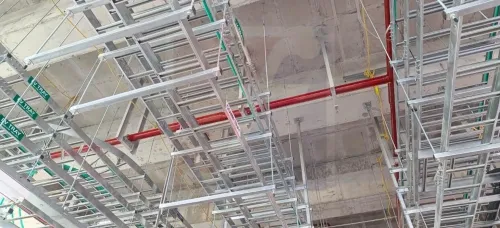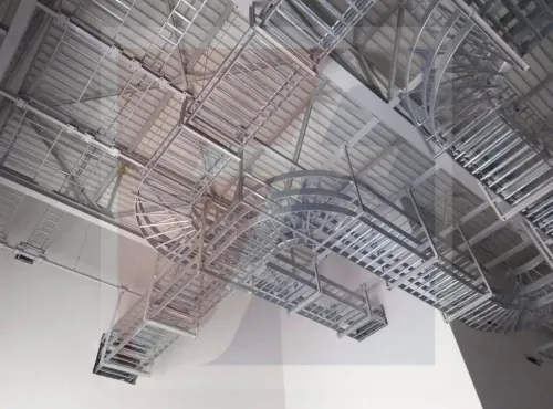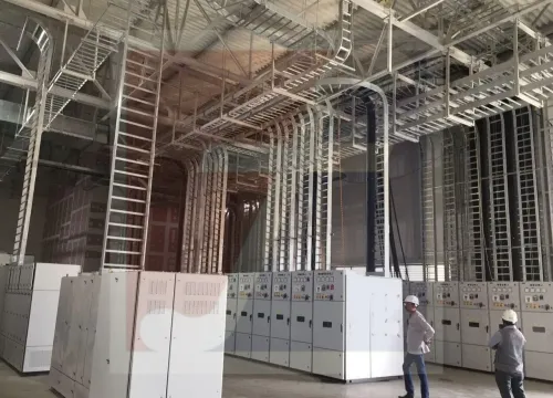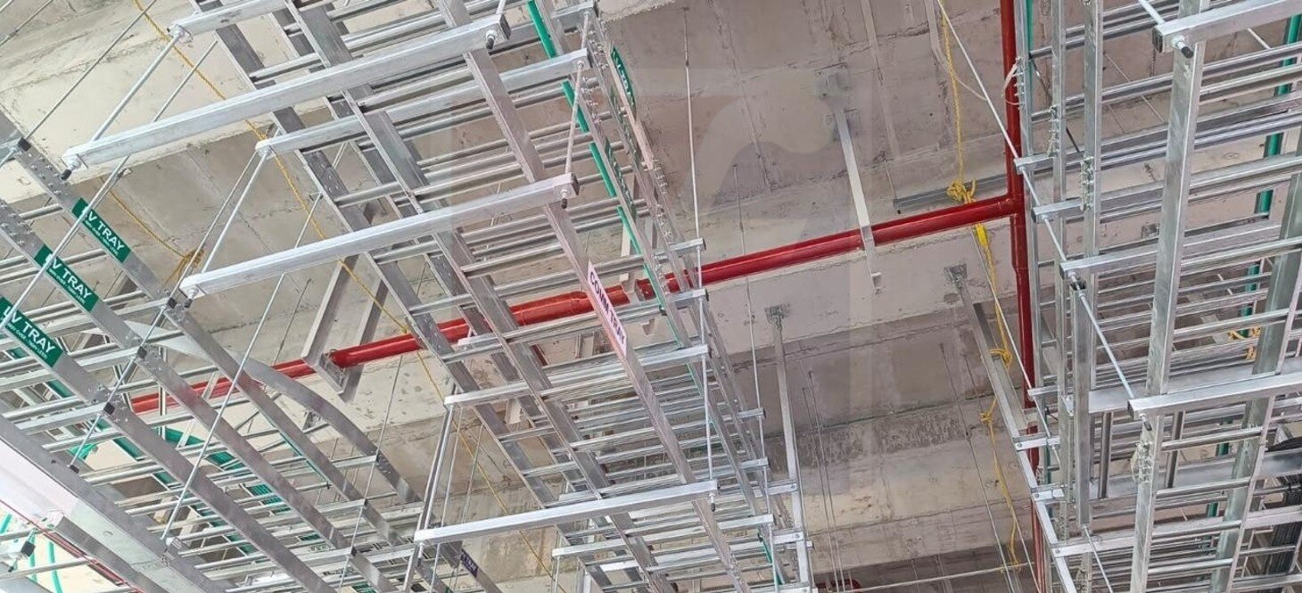
A ladder tray can look clean while its splice joints loosen, its supports overload, or its modified sections lose corrosion protection and electrical continuity. By the end, you will have a practical inspection schedule, a component-by-component checklist, and clear decision points for repairing, recalculating, or replacing an industrial cable tray route.
Key takeaways
- Inspect trays before energisation, after alterations, and during planned shutdowns.
- Tighten and document every splice, support, anchor, and bonding connection.
- Recalculate loading and deflection after adding, removing, or rerouting cables.
- Test bonding continuity and record approved repairs for future inspections.
Set the Inspection Schedule Before the Tray Carries Power
Inspect the industrial ladder tray before energisation, during commissioning, after every cable addition or alteration, and at defined shutdown inspection intervals. Set a cable tray maintenance schedule in the plant’s electrical maintenance plan; do not rely on a clean appearance as proof of serviceability.
- Before energisation, inspect side rails, rungs, splice plates, bolts, washers, supports, threaded rods, cantilever arms, hangers, covers, and tray-to-tray bonding connections. Confirm that covers match the tray system and have not reduced ventilation or access.
- During the commissioning inspection, verify the installed span and support arrangement against the manufacturer’s rated load/span data. Check for bent rails, loose rungs, misalignment, overloaded supports, damaged cable jackets, and unauthorized ties or clamps.
- After adding or rerouting cables, inspect again before restoring power. Confirm that the additions do not block drainage, impose point loads on individual rungs, damage jackets, or exceed the tray and support capacity.
- At each planned shutdown, inspect corrosion, missing hardware, displaced covers, cracked welds, coating loss at drilled edges, and bonding connections. Record defects with the tray route, location, photograph, and action.
Treat this work as electrical maintenance near conductors. De-energize, isolate, lock out and tag out, then verify absence of voltage before handling the tray or cables; only qualified persons may work on energized parts under the applicable electrical-work rules.
Never walk on tray rungs or use the tray as a platform—provide rated scaffolding, platforms, or walkways.
Inspect Every Mechanical Connection and Support
Find trouble by tracing the route from end to end, stopping at every joint and support. Check for corrosion, mechanical distortion, missing hardware, and unsafe access before touching the installation.
At each inspection point, compare the tray with its intended straight line and support arrangement:
- Inspect side rails and rungs for red rust, white zinc oxidation, blistered paint, coating loss at cut edges, cracks, bends, loose welds, and abrasion.
- Examine splice plates and bolts, including washers, for looseness, missing parts, elongated holes, trapped debris, and corrosion around the joint.
- Check threaded rods and cantilever arms for bending, cracked welds, damaged threads, shifted nuts, and overloaded or pulling supports.
- Inspect tray covers and hangers for displacement, broken fastening points, blocked drainage, and unauthorized attachments.
- Look for cable jackets that are cut, crushed, or abraded by sharp edges, clamps, ties, or distorted metal.
In outdoor or process areas, remove deposits and inspect beneath covers, around fasteners, and at cut edges. Water retention, salt, chemicals, and contact between dissimilar metals can start corrosion where the tray looks clean from a distance.
Treat the tray as a cable support, never as a ladder or work platform. Do not step on rungs or use covers as a standing surface; provide rated scaffolding, a platform, or a walkway. Replace a damaged cover only with one matched to the tray system, ventilation needs, environmental exposure, and falling-object requirements.
Recheck Loading, Deflection, and Cable Support After Changes
Confirm the installed route against the approved tray loading and support schedule before energisation and after every cable addition. Recalculate tray fill and cable weight; remaining empty space does not prove adequate capacity because added circuits can alter ampacity, grouping, ambient temperature, and heat dissipation.
Check support spacing against the tray manufacturer’s rated load/span data, not a generic distance. Account for tray width, material, cable weight, concentrated loads, and environmental loads. A longer replacement span can permanently deform the tray or pull splice connections apart.
Measure deflection at each loaded span and compare it with the manufacturer’s limit or the project design record. Investigate a sagging side rail, distorted splice, pulled threaded rod, or overloaded cantilever before adding cable. Do not walk on the tray rungs; use a rated platform or walkway.
Inspect the cable route after pulling and securing the cables. Verify the cable bending radius and sag at bends, drops, fittings, and terminations against the cable manufacturer’s minimum radius. A sharp temporary edge or a cable resting across one rung can damage insulation or exceed sidewall pressure even when the jacket looks intact.
Use approved clamps, ties, and support accessories that spread the load across the tray system. Confirm they do not crush jackets, block drainage, obstruct inspection, or overload individual rungs.
- Recalculate ampacity and tray loading.
- Record measured deflection and support condition.
- Check cable sag and separation after each change.
- Inspect firestop seals at penetrations; reseal any annular gap or damaged listed system.
Prove Bonding Continuity and Correct Field Modifications
Do not assume a metallic tray remains an effective grounding path after modification. With the circuit isolated, inspect every splice and measure electrical continuity across tray-to-tray bonding points using a continuity tester; investigate any open circuit or unexpected resistance against the project’s grounding criteria.
Check painted interfaces, dissimilar-metal transitions, loose hardware, and missing washers rather than relying on visual contact.
Before returning a modified section to service:
- Install bonding jumpers or listed bonding hardware where splice plates, coatings, or dissimilar metals interrupt the intended path.
- Keep expansion joints free to move, then verify that their bonding connection remains electrically continuous; a rigid bridge can restrain thermal movement, while a painted-over joint can break continuity.
- Deburr every cut edge and drilled hole. Remove loose coating and complete field-cut tray repair with a corrosion-protection system compatible with the original finish and the manufacturer’s instructions.
- Replace damaged splice plates, bolts, washers, or bonding hardware instead of tightening around cracks, stripped threads, or heavy corrosion.
- Seal or treat exposed steel where the specified finish requires it, but do not cover bonding contact surfaces with arbitrary paint.
- Recheck continuity after extensions, relocated sections, and replacement parts are installed.
Record the test point, instrument, result, repair coating, and hardware used. If impact, fire, or overload has buckled a side rail, distorted a rung, loosened a joint, or damaged the coating, operational cables do not prove the tray is safe; obtain a structural and electrical assessment before reuse.
Use Repair Records and Manufacturer Data to Decide the Next Action
A bent rail, cracked weld, missing splice bolt, or corroded cut edge is not automatically a repair. Compare the damage with the recorded cable load, support spacing, environment, and manufacturer load-span data before deciding whether the section can carry its original duty.
| Action | Decision rule | Required evidence |
|---|---|---|
| Repair | Damage is local, the rails and rungs remain aligned, and the original load path can be restored | Approved splice hardware, compatible corrosion repair, and an updated inspection record |
| Assess | Damage affects a support, bend, splice, fire barrier, or loaded section, or the original design information is missing | Review by a competent engineer using site measurements and industrial cable tray manufacturer data |
| Replace | A rail is buckled, a weld is cracked, a splice connection is permanently distorted, or corrosion has reduced the section materially | New section, verified supports, bonding, and post-work inspection |
Do not improvise a repair with extra holes, cable ties around sharp edges, or point-loaded clamps. Use listed tray accessories or manufacturer-approved parts, preserve drainage and inspection access, deburr every field cut, and restore corrosion protection with a coating compatible with the original finish.
Check firestop at penetrations after any replacement or cable addition. A tray cannot restore a wall or floor’s fire rating; use a compatible listed firestop system and reseal damaged or newly exposed annular spaces.
For sections supplied by Fixotech Engineering Systems Pvt Ltd: Manufacturer of Cable Management Systems, keep the approved splice, finish, accessory, and load-span documents with the asset record. Close the record only after photographs, torque checks, bonding continuity, support spacing, and the next inspection date are documented.
Related products
 | LADDER CABLE TRAY Other common name in Cable tray industry is ladder tray. Simple design consisting of side rails with rungs connected. View product → |
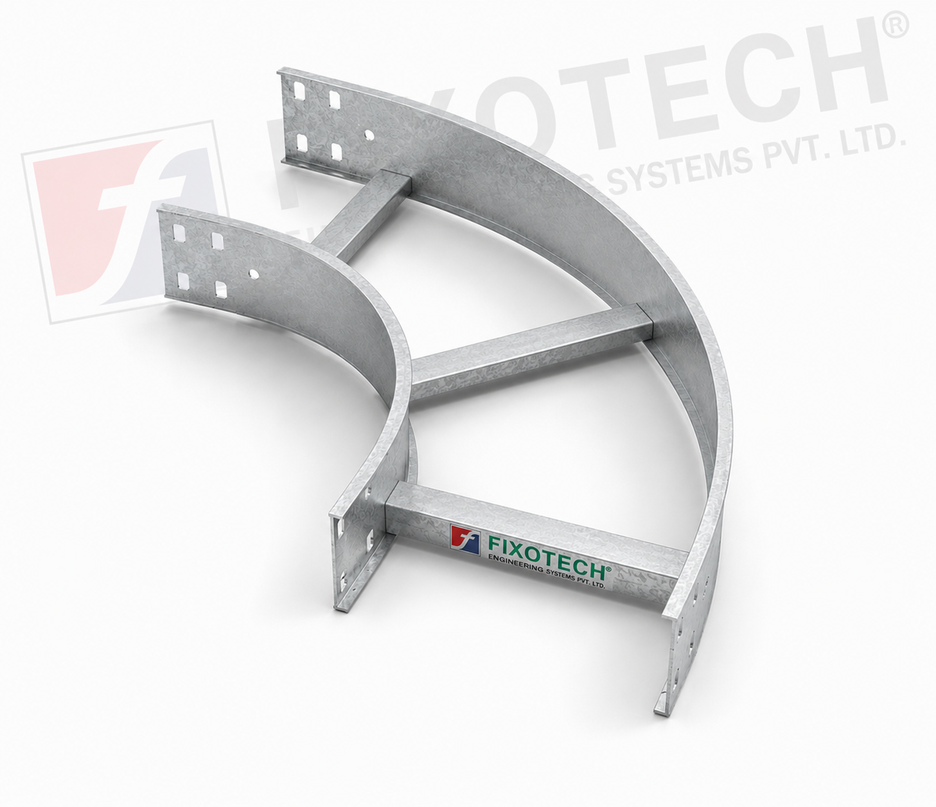 | LADDER CABLE TRAY The purpose of a horizontal ladder bend cable tray is to make it easier for cables to be routed around bends or corners in horizontal cable... View product → |
Frequently asked questions
When should you inspect an industrial ladder cable tray?
Inspect it before energisation, during commissioning, after every cable addition or alteration, and at defined shutdown intervals.
What mechanical parts require inspection?
Check tray splices, bolts, supports, anchors, covers, fittings, and signs of corrosion, distortion, loosening, or inadequate support.
What must you recheck after adding or rerouting cables?
Recheck tray loading, cable support, span deflection, clearances, bend routes, and the capacity of supports affected by the change.
How do you verify cable tray bonding continuity?
Inspect bonding jumpers and field modifications, then test electrical continuity across tray sections and record the test result.
How should repair records guide the next maintenance action?
Compare the defect, repair, test result, manufacturer data, and recurrence history to decide whether to monitor, repair, replace, or redesign the installation.
Related products
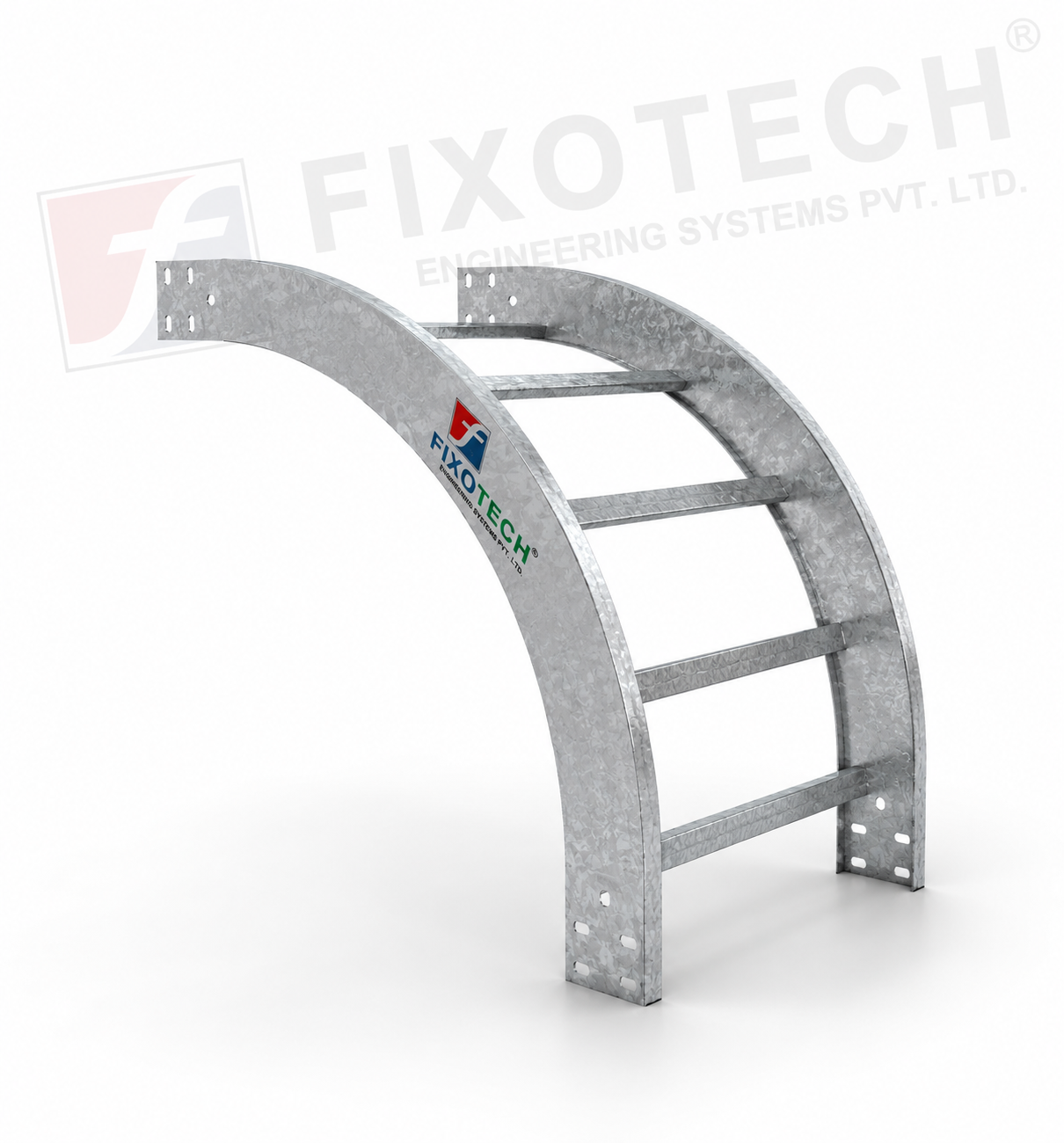 | LADDER CABLE TRAY A particular kind of cable tray called a vertical bent ladder cable tray is made to make it easier to route wires in vertical cable management... View product → |
 | LADDER CABLE TRAY One particular kind of cable tray made to make it easier to route wires at cross junctions in horizontal cable management systems is the cross-bend... View product → |
 | LADDER CABLE TRAY One particular kind of cable tray made to make it easier to route cables at T-junctions in horizontal cable management systems is the ladder tee bend... View product → |
 | RACEWAY CABLE TRAY - CEILING RACEWAY RACEWAY CABLE TRAY - CEILING RACEWAY A cable management system made especially for routing and arranging cables over ceilings or overhead spaces is called a ceiling raceway cable tray. View product → |