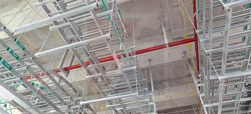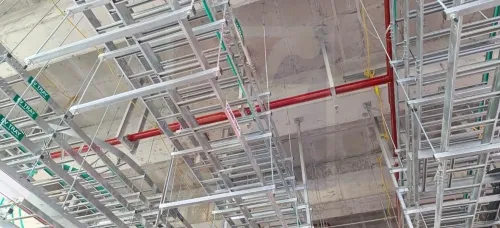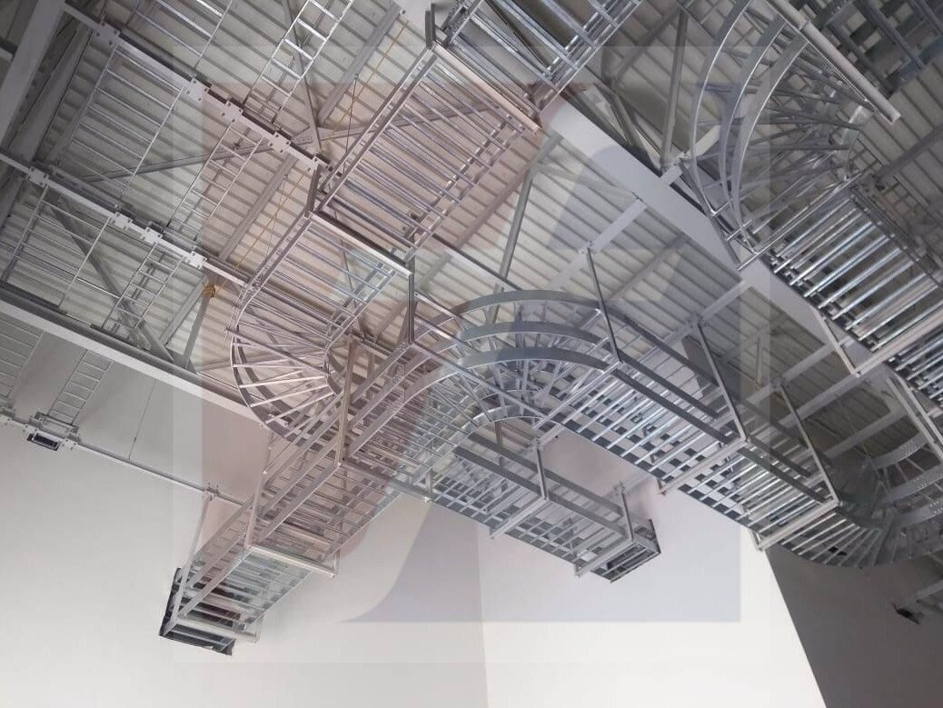
The right choice depends on more than whether a ceiling route is available. By checking access, cable behaviour, fire and electrical requirements, support conditions, and maintenance demands, you can decide whether an enclosed ceiling raceway fits—or whether another pathway will perform better.
Key takeaways
- Confirm ceiling clearance for the tray, bend radius, cover and technician access.
- Choose open tray, conduit, basket or floor routing when access or separation demands it.
- Check fill, heat, bend radius and circuit separation before specifying raceway size.
- Require support, bonding, fire, corrosion and jointing details in manufacturer documents.
Start with the Facility: Is a Ceiling Raceway Physically and Operationally Suitable?
A ceiling raceway suits your facility only when the ceiling void height leaves room for the tray, cable bend radius, cover removal and a technician’s hands.
Map access panels before fixing the route, then check clearances around HVAC ducts, sprinklers, lights and structural members; a route shown on a reflected ceiling plan is not maintenance access.
Reject the arrangement when technicians cannot reach bends, junctions, covers and cable exits for inspection, replacement or routine cable additions without removing building services or using unsafe access equipment. Treat these conditions as warning signs:
- Inaccessible ceilings or insufficient ceiling void height
- High ambient heat, washdown zones or corrosive atmospheres
- Heavy bundled cables that overload the support system or restrict heat dissipation
- Frequent reconfiguration that demands open, easily reached pathways
- A requirement for continuous visual inspection or ventilation
A covered raceway protects small cables from falling contaminants but hides damage and restricts cooling. An open tray improves inspection and ventilation, so choose the enclosure only when protection outweighs those penalties. Confirm that supports attach to concrete or structural steel, not a suspended-ceiling grid, and include cable weight, fittings and future capacity.
Apply the fire strategy before installation: a raceway crossing a rated wall or floor needs a listed or tested fire-rated penetration detail that preserves the assembly’s rating. A tray, cables and generic sealant assembled on site is not equivalent to a tested penetration system.
Compare the Raceway with Open Tray, Conduit, Basket and Floor Routes
A ceiling raceway suits small cables or areas exposed to falling contaminants because its enclosure improves dust and impact protection. It also hides cable damage, restricts ventilation and makes inspection harder. Compare the pathway against the facility’s dominant risk, not its appearance.
| Option | Visibility and ventilation | Protection and upkeep | Change and access |
|---|---|---|---|
| Enclosed ceiling raceway | Low visibility; weakest heat dissipation | Best against dust and falling debris; cover removal slows cleaning | Moderate installation effort; neat expansion but limited access |
| Covered perforated tray | Partial visibility; reduced airflow | Protects small cables from contaminants; cover complicates inspection | Moderate effort; additions require cover removal |
| Open perforated cable tray | High visibility and good cooling | Exposes cables to dust, impact and cleaning damage | Easy additions and inspection; needs clear working access |
| Ladder tray | Excellent airflow and inspection | Least protection from falling objects and impact | Efficient for large cables; fittings and access remain straightforward |
| Conduit | No visibility or airflow | Strongest mechanical protection and circuit segregation | Highest pulling effort; bends and new cables make changes difficult |
| Suspended basket tray | High visibility and airflow | Limited dust and impact protection; easy to clean around | Fast installation and reconfiguration; cables remain exposed |
| Floor raceway | Access at floor level; ventilation depends on enclosure | Protects cables but faces traffic, finishes, spills and water | Preserves ceiling space; future work disrupts occupied areas |
Select the route that controls the main hazard: enclosure for contaminants, open tray for heat and inspection, conduit for severe impact or segregation, basket for frequent changes, and floor raceway when ceiling congestion dominates. Verify that technicians can reach every bend, cover and cable exit safely.
Verify Capacity, Heat, Bend Radius and Circuit Separation Before Sizing
A tray can have spare physical space and still overheat cables or fail under their weight. Treat tray fill, ampacity derating, bend geometry and circuit separation as separate design checks.
1. Calculate tray fill under NEC Article 392 using each cable’s outside diameter or manufacturer area data. Add a defined future capacity allowance, such as a project-approved reserved percentage or spare width, rather than leaving “some room” by judgment.
2. Check ampacity under NEC Article 392.80 for the conductor arrangement and number of current-carrying conductors. A full-looking tray may need larger conductors, wider spacing or a different wiring method when heat buildup reduces allowable ampacity.
3. Compare total cable weight, including the future capacity allowance, with the manufacturer’s load table for the actual span, fitting and support arrangement. Do not use a nominal tray-width load rating.
4. Draw horizontal bends, tees, crosses, reducers and vertical bends from the largest cable’s minimum bend radius. Provide straight length for pulling, dressing and future replacement; a compact fitting that damages cable jackets is not a space saving.
5. Assign separate pathways, dividers or spacing for power, control, instrumentation, data and intrinsically safe circuits. A divider is not automatically sufficient for EMC or hazardous-location requirements: specify shielded cables, grounded metallic separation or separate trays where the governing design requires them.
Include metallic separation, shielding, bonding and equipment-grounding provisions. Bolted tray sections do not by themselves prove fault-current continuity; specify listed bonding provisions or jumpers and verify continuity across joints, coatings and transitions.
Check the Support, Jointing, Fire, Corrosion and Bonding Details
A tray that fits the drawing can still fail its rated load, fire, corrosion, or fault-current performance. Require hanger supports fixed to concrete or structural steel, never a suspended-ceiling grid, and calculate the loaded tray, fittings, covers, and future capacity.
Check span, hanger type, support spacing, joint locations, and seismic requirements against NEMA VE 1 load and test data and NEMA VE 2 installation guidance.
- Specify manufacturer-approved jointing hardware, cover retention, edge protection, and field-cut treatment so cables cannot contact sharp metal.
- Require a listed or tested firestop penetration detail where the tray crosses a rated wall or floor; do not accept an improvised tray, sealant, and cable combination.
- For long runs or building movement, obtain the manufacturer’s expansion joints detail, allowable movement, support rule, bonding method, and cable slack arrangement.
- Match galvanized steel, aluminum, stainless steel, or painted finishes to moisture, chemicals, coastal air, and washdown exposure.
- Confirm fastener compatibility and prevent trapped water at overlaps, fittings, drilled holes, and supports.
Bolting sections together does not prove bonding continuity. Verify the fault-current path across joints, painted surfaces, expansion fittings, nonmetallic transitions, and dissimilar-metal interfaces using specified bonding jumpers or listed provisions. Grounding the tray also does not replace cable-conductor equipment grounding where the governing code requires it.
A field-made gap without the specified bonding and slack arrangement is not a proper expansion solution.
Use Manufacturer Documentation to Make the Final Go-or-No-Go Decision
Approve a ceiling raceway only when the manufacturer supplies system-level documentation for the exact tray, span, fitting and support arrangement. Compare manufacturer load tables with NEMA VE 1 ratings and apply NEMA VE 2 installation guidance; a nominal maximum load is not enough.
Request these documents before issuing a purchase order:
- System-specific load and span tables, including future cable capacity
- Fitting-radius limits for horizontal bends, tees, crosses and vertical bends
- Support, hanger and structural attachment details
- Cover, divider, cable separation and access-panel drawings
- Bonding provisions across joints, painted surfaces, expansion fittings and transitions
- Expansion instructions, allowable movement and cable-slack requirements
- Corrosion compatibility guidance for the atmosphere, fasteners and field cuts
- Field-cut treatment and complete installation instructions
Confirm that every proposed cable is permitted under the governing code, including listed tray cable where required. Ordinary building cable does not become compliant because it sits in a tray. Reject a visually similar fitting or support: it can change the tested system basis.
Require drawings that show bend access, fire-rated penetrations and clearances from sprinklers, HVAC, lighting and structural members.
| Decision record | Evidence required | Redesign trigger |
|---|---|---|
| Raceway wins | Lower lifecycle effort than conduit, basket, open tray or floor raceway | Access, heat or separation fails |
| Supplier passes | Complete project-specific documentation | Missing load, bonding or corrosion data |
Consider Fixotech Engineering Systems Pvt Ltd: Manufacturer of Cable Management Systems alongside other manufacturers only after it supplies this evidence for the specified installation, cable classes and environment. Record why the raceway beats each alternative.
Related products
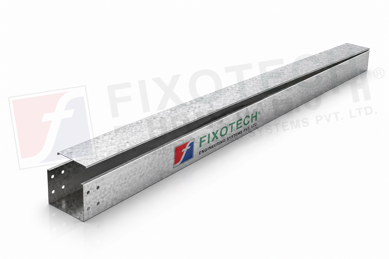 | RACEWAY CABLE TRAY - CEILING RACEWAY RACEWAY CABLE TRAY - CEILING RACEWAY A cable management system made especially for routing and arranging cables over ceilings or overhead spaces is called a ceiling raceway cable tray. View product → |
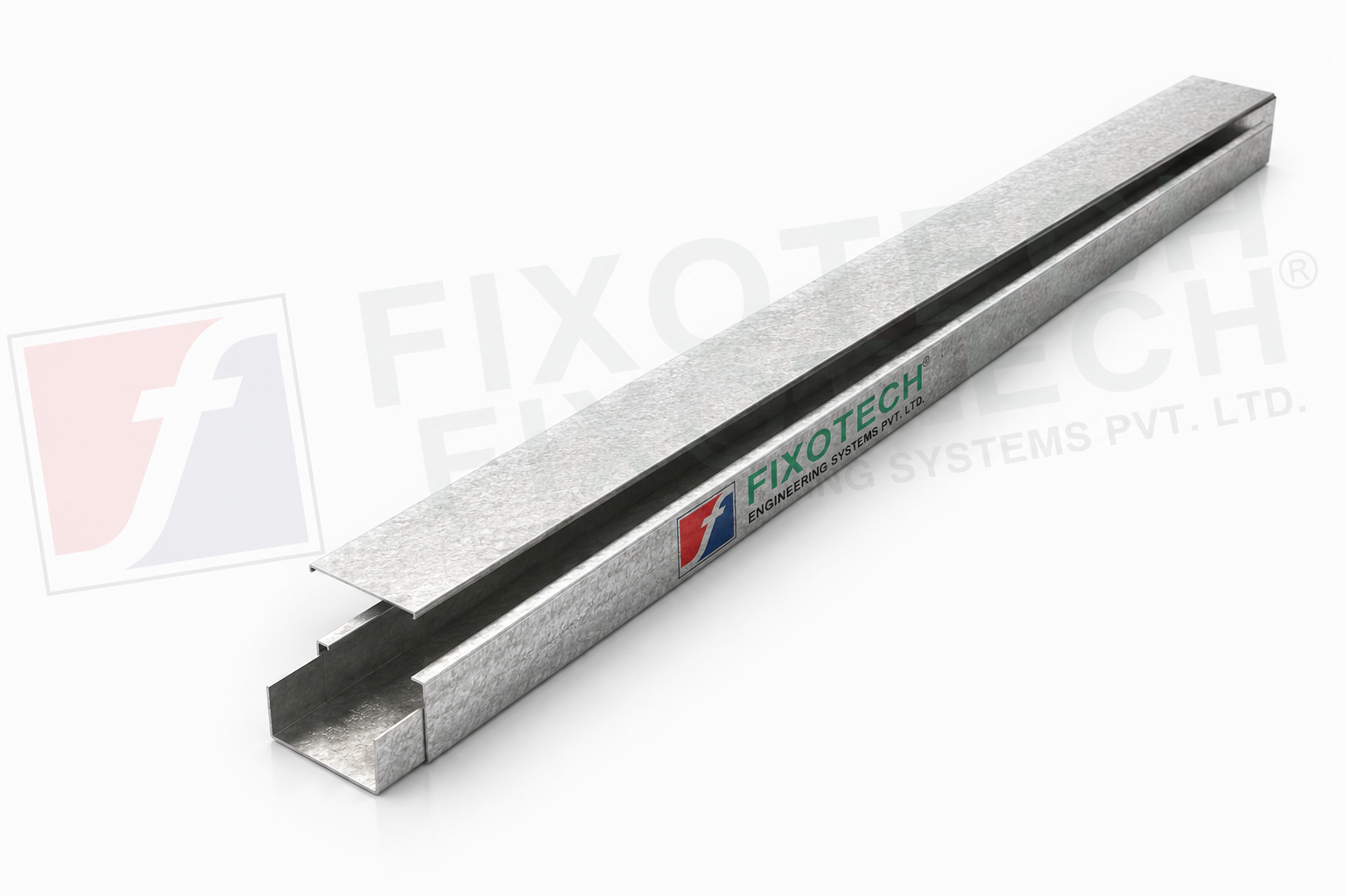 | RACEWAY CABLE TRAY - FLOOR RACEWAY RACEWAY CABLE TRAY - FLOOR RACEWAY A cable management system called a floor raceway cable tray, or just a floor raceway, is used to route and safeguard wires between floors, especially... View product → |
Frequently asked questions
When is a ceiling raceway physically suitable for a facility?
Use one when the ceiling void leaves room for the tray, cable bend radius, cover removal and technician access.
How does a ceiling raceway compare with open tray, conduit, basket and floor routes?
Compare access, protection, cable separation, space, installation effort and future changes before selecting the route.
What must you verify before sizing a ceiling raceway?
Check cable capacity, heat dissipation, minimum bend radius, circuit separation and allowance for future cables.
Which manufacturer details support a final go-or-no-go decision?
Review support spacing, jointing method, fire performance, corrosion protection, bonding provisions and installation documentation.
Related products
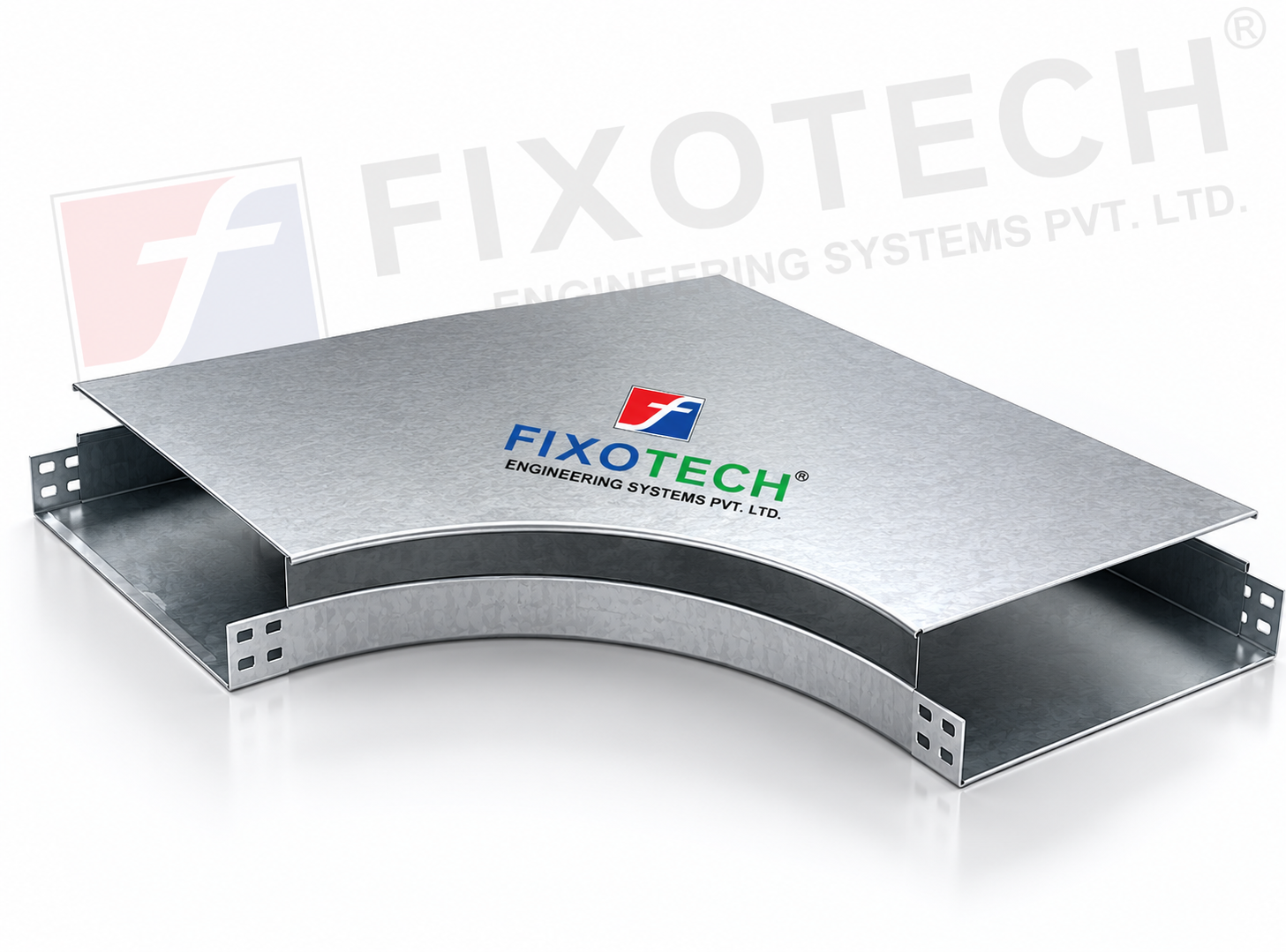 | RACEWAY CABLE TRAY - CEILING RACEWAY One part of a cable management system that helps with the seamless movement of cables around corners or horizontal bends is the Raceway Horizontal... View product → |
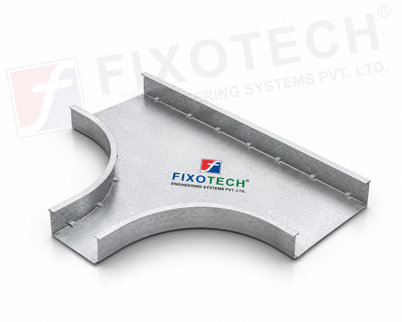 | RACEWAY CABLE TRAY - CEILING RACEWAY One particular part of a cable management system made to help with the seamless transition of cables at intersections or T-junctions in a raceway... View product → |
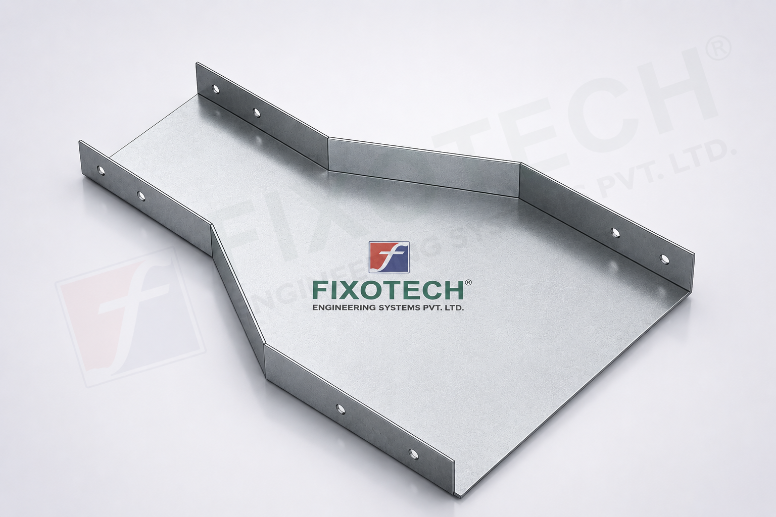 | RACEWAY CABLE TRAY - CEILING RACEWAY REDUCER To move between raceway sections of various widths or capacities, cable management systems use reducer raceway cable trays. |
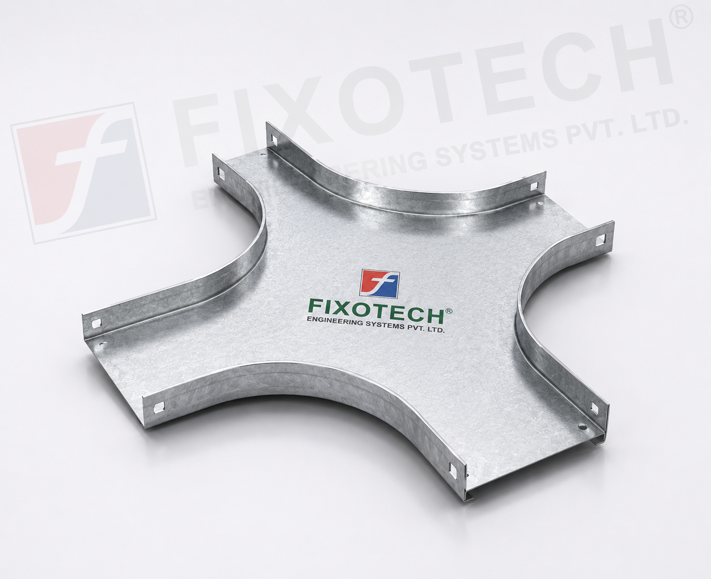 | RACEWAY CABLE TRAY - CEILING RACEWAY One part of a cable management system that helps with the seamless transfer of cables at cross intersections or junctions in a raceway system is the... View product → |