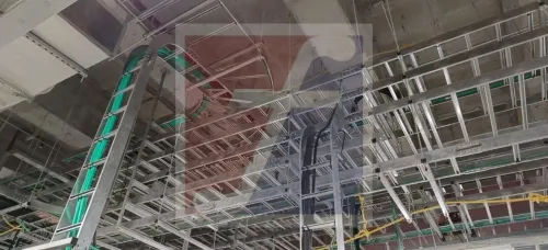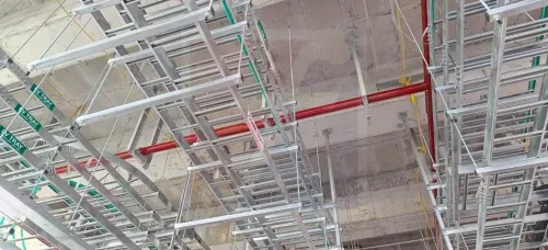
A tray replacement can damage cables, overload supports, interrupt bonding, or compromise a fire-rated barrier if you treat it as a simple removal and refit. You will be able to survey the existing route, protect the cable bundle during the changeover, specify a compatible replacement, and verify the finished installation before energising it.
Key takeaways
- Measure cable load, support spacing, route length, and required clearances before ordering.
- Isolate and lock out circuits, then support cables independently before removing the tray.
- Match tray material, finish, fittings, bend radius, and environment—not just tray width.
- Inspect bonding, firestopping, cable separation, and test results before energising circuits.
Survey the existing route and prove the replacement will carry the load
Measure the route before ordering anything. An existing cable tray inspection must establish what the tray carries, how it is supported, and what the replacement must reproduce or improve—not merely its nominal width.
Record these items at every straight run, bend, riser, and transition:
- Tray width and depth, side-rail height, material, thickness, coating, perforation pattern, and cover arrangement
- Cable identities, outer diameters, lengths, weights, conductor arrangement, ampacity requirements, and unused capacity
- Support type, spacing, cantilever length, elevation, deflection, corrosion, damaged fasteners, and splice-plate pattern
- Route length, bend radius, wall or floor penetrations, fire barriers, obstructions, and clearance from heat sources
- Grounding and bonding jumpers, continuity across joints, dividers, cable cleats, and any classified-location requirements
- Existing and planned covers, dividers, concentrated loads, environmental loads, and future-cable allowance
Perform a cable fill calculation using the actual cable diameters and the selected tray’s fill rules. Then calculate cable weight per metre and add the tray, covers, dividers, fittings, future allowance, and specified environmental or concentrated loads. Do not treat the tray as a walkway.
Compare that total with the replacement manufacturer’s load-versus-span rating. A wider tray, heavier bundle, cover, or change from ladder to perforated tray can require closer supports. Place splice joints between supports where the tested system permits, and verify ampacity under NEC Article 392.22 and 392.80; check bonding under Article 392.60.
Isolate the circuits and support the cables before disconnecting the tray
A qualified person must complete lockout tagout before touching the tray. Identify every circuit, connected panel, motor, transformer, UPS, generator, control supply, and possible backfeed source. Open the correct disconnects, apply personal locks and tags, and prove dead at the work point with a suitable tester.
Establish an exclusion zone below and around the work area.
- Confirm that the isolation covers every cable in the section, not only the equipment named on the work order. Test phase-to-phase and phase-to-earth, and verify the tester on a known live source before and after testing.
- Inspect the section for cables that cannot be removed or supported independently. Do not rely on a partially disconnected tray, splice plates, covers, or adjacent equipment to carry the bundle.
- Install temporary cable supports before loosening any tray connection. Place temporary cable supports close enough to prevent excessive sag, preserve each cable’s minimum bending radius, and keep the load away from glands, terminals, joints, and equipment entries.
- Use temporary cleats and slings rated for the cable weight, with padding that will not cut or crush the jackets. Support cables from below or with approved lifting points; never pull them sideways to create clearance.
- Transfer the cable weight gradually, then check that no cable is hanging from a termination and that no force reaches adjacent equipment. Support the remaining tray independently before removing the damaged section.
Keep workers off the tray unless its design specifically permits access. A cable bundle left hanging for even a short removal operation can pull terminals loose, distort glands, or overload the next tray section.
Choose the tray type, material, finish, and fittings for the actual environment
Select the replacement by environment and cable arrangement, not width alone. Recheck NEC Article 392.22 fill and 392.80 ampacity for cable count, conductor size, spacing, construction, and ambient temperature; a new bundle layout can run hotter in the same tray.
| Option | What it means | When it applies |
|---|---|---|
| Perforated tray versus ladder tray | Perforations provide drainage and frequent fixing points; ladder construction improves ventilation and restraint for large cables but changes support and cleat requirements. | Retain perforated tray for small or mixed cables needing continuous support; choose ladder only after checking cable support, sag, bending radius, and ampacity. |
| Pre-galvanised steel tray | Zinc coating is applied before fabrication, leaving cut edges and drilled areas less protected. | Use in dry, low-corrosion interiors where the selected system and cut-edge treatment permit it. |
| Hot-dip galvanised cable tray | Zinc coating covers fabricated steel, giving stronger protection for exposed service and field damage. | Use outdoors or where humidity, washdown, or moderate chemical exposure demands a more robust finish. |
| Stainless steel cable tray | Resists corrosive moisture and selected chemicals without relying on a zinc coating. | Specify the correct stainless grade after checking chloride, chemical, and temperature exposure. |
| Painted or coated steel | Adds a specified barrier finish but depends on coating integrity and compatible fasteners. | Use only where the coating system, repair method, and environment are documented. |
Match splice plates, fasteners, covers, bends, reducers, clamps, and support spans to the system rating. Treat every field cut with the specified corrosion repair; sharp edges, blocked drainage, unsupported fittings, and excessive deflection can damage cables. Bond metallic sections and verify continuity under NEC 392.60, including across painted joints.
Restore cable grouping for thermal and EMC behaviour, then give Fixotech Engineering Systems Pvt Ltd: Manufacturer of Cable Management Systems the measured route, exposure, cable data, and fitting schedule rather than only the tray width.
Transfer each cable without exceeding its bending and pulling limits
A sharp reducer, vertical bend, or tray edge can damage a cable before it reaches the straight run. Before moving each cable, compare the route with the cable manufacturer’s limits:
- Confirm every inside bend and transition exceeds the cable’s minimum cable bending radius.
- Confirm the planned pull stays below the permitted cable pulling tension.
- Check that bend rollers and fittings keep sidewall pressure below the cable’s stated limit.
- Measure tray fittings take-off dimensions so the cable does not kink, lift, or enter a gland at an abrupt angle.
Install temporary cleats, slings, or independent supports before releasing the old tray. Place supports close enough to prevent sag and keep the cable’s weight off glands, terminals, joints, and equipment entries. Do not pull a cable sideways to create clearance or leave it hanging from a termination.
Move cables one at a time, using a draw rope or controlled hand movement rather than dragging the jacket across steel. Fit rollers or padded sheaves at every change of direction, and cover field-cut tray edges with approved edge protection. Stop if the jacket twists, flattens, scrapes, or catches.
Lower each cable into the new tray without dropping it, then restore its planned separation, cleating, and bend direction. Keep joints supported without clamping the joint body, and leave enough slack for the documented entry geometry. Check glands and terminals for movement before removing the temporary supports.
Inspect, bond, firestop, and test the completed replacement
Before re-energisation, complete a cable tray replacement inspection against the approved layout and manufacturer’s load/span rating. Confirm every support is installed at the specified spacing, splice hardware is present and tight, fittings are supported, deflection is acceptable, and no tray edge can damage a cable.
Check the completed tray for:
- Correct width, cover, elevation, route, and cable fill
- Secure transitions, bends, expansion joints, and end fittings
- Clear drainage openings and no trapped water
- No displaced cable, excessive unsupported span, or pulled gland
- No missing labels, sharp edges, or loose hardware
Prove electrical continuity across every metallic tray section, splice, fitting, expansion joint, and transition with a low-resistance continuity test. Do not infer bonding from contact between painted or corroded parts. Install cable tray bonding jumpers where continuity is interrupted, and verify the tray’s connection to the equipment grounding conductor and grounding system.
Restore circuit labels, phase identification, cable grouping, and warning signs at the tray and connected equipment. At each wall, floor, or fire barrier, inspect the compatible listed firestop system for the barrier type, tray configuration, cable types, and permitted loading; ordinary sealant is not a substitute.
Remove temporary supports only after the tray carries the load. Perform insulation-resistance, phase, polarity, or functional tests required by the outage plan and equipment risk assessment. Re-energise only after covers, guards, tools, personnel, and test leads are clear and an authorised person releases the circuit.
Frequently asked questions
What must you survey before replacing a perforated cable tray?
Record the cables carried, route dimensions, support spacing, tray condition, cable weight, clearances, bend requirements, and the replacement tray’s load capacity.
How do you make a cable tray replacement safe before disconnecting the old tray?
Identify and isolate the circuits, apply lockout and tagout, verify dead conductors, and install independent temporary supports for the cables.
How do you choose a replacement perforated cable tray?
Select the tray type, material, finish, fittings, load rating, corrosion resistance, and dimensions for the installation’s environment and cable arrangement.
What must you check after transferring cables to the new tray?
Check bend radii, cable damage, separation, tray bonding, supports, firestopping, gland and termination condition, continuity, insulation, and circuit test results.