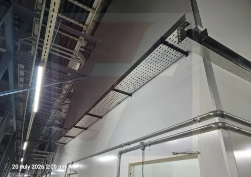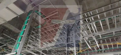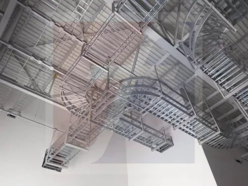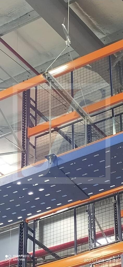
Four tray directions meeting at one point create a geometry problem that two bends, a tee, or improvised cuts can leave unresolved. By checking the route plan, cable radius, tray compatibility, capacity, supports, and installation details, you can specify a cross bend that fits the system rather than merely looking correct on paper.
Key takeaways
- Use a horizontal cross when four tray directions meet at one plan-view junction.
- Match cross width, side height, material, finish, and hole pattern to the tray system.
- Set the bend radius from the largest cable’s minimum allowable bending radius.
- Verify alignment, fasteners, covers, and cable support before energising the route.
When a cross bend is the right geometry for four tray directions
A horizontal cross is the right geometry when four tray directions must remain connected at one plan-view junction. For example, power cables enter from the west and exit east along the main route; control cables enter from the north; instrumentation cables enter from the south and exit through the remaining connected branch toward their equipment.
The four-way intersection keeps each route continuous without building two horizontal bends or separate tray runs.
A cross provides four connected directions. A tee provides one main route and one branch only, so it suits a north control take-off from an east-west power route but not a junction requiring east, west, north, and south paths.
This tee bend comparison is the key distinction: choose a cross fitting for four connected directions, not merely because both fittings change a route.
- Use a horizontal cross for a horizontal four-way intersection where the tray branches must meet at one junction.
- Do not treat the cross as an elevation solution. A rise or drop requires a vertical inside or outside bend as well.
- Reject it when the route has only one branch, when congestion demands greater segregation, or when power, control, and instrumentation need separate trays or dividers that cannot continue through the fitting.
- Reject it when a cable’s minimum bend radius exceeds the fitting’s throat or inner path.
- Use an accessible junction box instead when maintenance access, termination, or cable pulling requires an open service point.
How to select the radius, capacity, and cable path
Choose the radius from the cable, not the tray catalogue. The minimum allowable bending radius is the cable manufacturer’s limit; the fitting’s bend radius is the geometric curve provided by the cross.
| Radius | Selection test | Failure if undersized |
|---|---|---|
| 300 mm radius | Use only when every cable permits it and every throat clears | Cable sheath, screen, or conductor stress |
| 600 mm radius | Use when the manufacturer’s limit and inner path require more room | Inner corners can still restrict the route |
| 900 mm radius | Use when large single-core, medium-voltage, fibre-optic, or screened cables demand it | A standard fitting cannot override the cable requirement |
Measure the fitting from the cable centreline, not the tray’s inside or outside edge. Tray width describes lateral space; bend radius describes the curve available to the cable. Trace the most restrictive inner-radius path through every throat and branch, including the point where the route divides into four branches.
Complete the fill calculation before approving the fitting:
- Obtain the fitting’s usable area and approved fill limit.
- Calculate cable area, or apply the specified fill method, for each incoming and outgoing leg.
- Check the controlling throat, not only the straight tray sections.
- Apply the existing load rating independently to every leg; a cross does not increase tray load or fill capacity.
Maintain cable separation for power, control, instrumentation, data, and fire-alarm circuits. Use separate trays, compatible dividers, or a documented segregation method that continues through the cross; an open-looking intersection provides no separation by itself.
How to prove the cross matches the perforated tray system
Prove the cross matches before ordering it: check tray width and height for every branch, side-rail profile, flange orientation, perforation pattern, material and finish, and connection-hole layout. A matching width alone does not prevent misaligned splice holes or incompatible flanges.
Require plan view and elevation drawings showing handedness, inward or outward transitions, branch directions, equipment location, cover pieces, dividers, and reducer placement. When widths change, place a reducer before or after the cross unless the supplier confirms an integrated unequal-width fitting; never assume a standard cross accepts different branch widths.
Choose the construction against the exposure.
| Material or treatment | Suitable environment | Main check |
|---|---|---|
| Galvanised steel | General outdoor or industrial service | Confirm coating continuity after cutting and joining |
| Stainless steel | Corrosive, saline, or washdown areas | Specify the grade and match all hardware |
| Aluminium | Weight-sensitive routes and selected corrosive locations | Isolate it from dissimilar metals |
| Protective coatings | Hot, chemically exposed, or demanding service | Confirm temperature range, repair method, and coating compatibility |
Check continuity across tray, fitting, splice plates, bolts, and supports. Mixing galvanised steel, stainless steel, and aluminium without isolation can accelerate galvanic corrosion in wet or saline locations.
Verify the project documents before release:
- Tray dimensional and loading schedules
- Segregation rules and bonding requirements
- Fire stopping details
- Expansion tables and installation acceptance criteria
Confirm that the cross preserves bonding across joints and finishes; a coated fitting is not automatically electrically continuous. Ensure fire stopping remains possible around each branch and cover.
How to install the junction without weakening the route
Factory-made cross bend usually gives better alignment, controlled edges, and repeatable joining than four field-cut tray sections assembled with couplers. Field cutting removes side-rail material, distorts splice holes, creates sharp edges, adds labour, makes support uncertain, and increases inspection effort.
1. Use the manufactured fitting when the junction carries substantial load or includes covers and dividers. If field modification is approved, complete deburring field modifications on every cut edge, apply an approved edge guard or corrosion repair, and check that cable insulation cannot contact metal.
2. Position supports near fitting, then support each branch wherever its load arrangement requires. Prevent twisting and preserve the load path across the junction; do not place straight-run splice plates directly at a support unless the fitting detail permits it.
3. Confirm dedicated cross covers, divider continuity, clamp locations, drainage, ventilation, cable retention for small cables, and closure of unused branch openings. Straight covers can leave gaps or foul cables.
4. Follow the system’s expansion tables: keep expansion gaps and thermal movement away from the complex junction. Inspect metallic continuity across painted joints, expansion joints, and nonconductive finishes; provide earthing and install bonding jumpers when the project specification requires them.
What to put on the order and how to validate the finished fitting
Put the fitting on a controlled order, not a radius alone. The procurement checklist must state:
- Drawing revision; tray width and side-rail height for every branch; horizontal or vertical geometry; inside and centreline radius; branch directions and angles; material and finish; perforation and hole pattern; cover and divider needs.
- Joining hardware, support spans and support details, cable type, minimum bend radius, expansion provisions, offsets, and delivery tolerances.
- Existing tray compatibility, required load information, bonding, drainage, and inspection points. Request plan and elevation shop drawings showing orientation, hole layout, covers, dividers, and any reducer.
For a worked example, specify a 600 mm tray carrying power east-west, control north, and instrumentation south. Select the smallest radius that meets the cable manufacturer’s centreline bend requirement and passes the inner-throat check on all four paths.
Reject the option if the cable requires a 900 mm radius or the support layout cannot carry the cross.
Validate the delivered fitting against the approved drawing: measure each branch, confirm branch directions, side-rail height, perforations, joining holes, finish, cover fit, divider continuity, and edge protection. Common ordering errors include assuming straight-tray load ratings, interchangeable hole patterns, or standard covers.
Fixotech Engineering Systems Pvt Ltd is relevant when custom geometry needs checking against an existing perforated tray; require dimensional drawings and compatibility confirmation.
Include survey time, shop-drawing revision, cable slack, support installation, and final inspection in the programme. A fitting that arrives on time but cannot align or close is not a completed delivery.
Frequently asked questions
When is a cross bend the right geometry for a cable tray route?
Use a horizontal cross when four tray directions must remain connected at one plan-view junction, such as west-east, north, and south routes.
How do you select the radius and capacity of a cross bend?
Base the radius on the largest cable’s minimum bending radius, then check tray width, side height, fill, weight, and separation requirements.
How can you prove a cross matches a perforated cable tray system?
Compare the cross with the tray’s width, side height, material, finish, perforation pattern, splice arrangement, and accessory dimensions.
How do you install a cross junction without weakening the route?
Align each connected tray, use the specified splice plates and fasteners, support the fitting near its joints, and avoid drilling holes that compromise its load path.
What information belongs on an order for a cross bend?
Specify tray type, width, side height, material, finish, radius, branch directions, cable duty, quantity, and required covers, supports, and splice hardware.