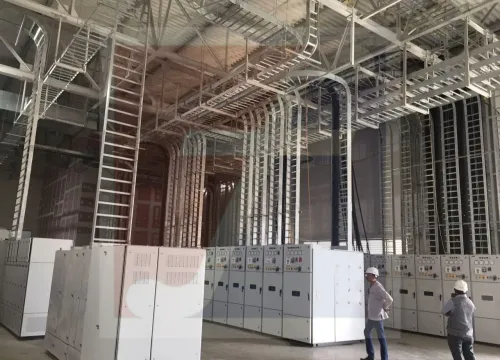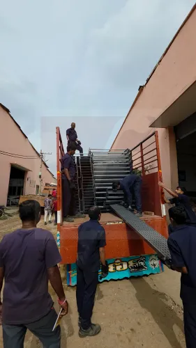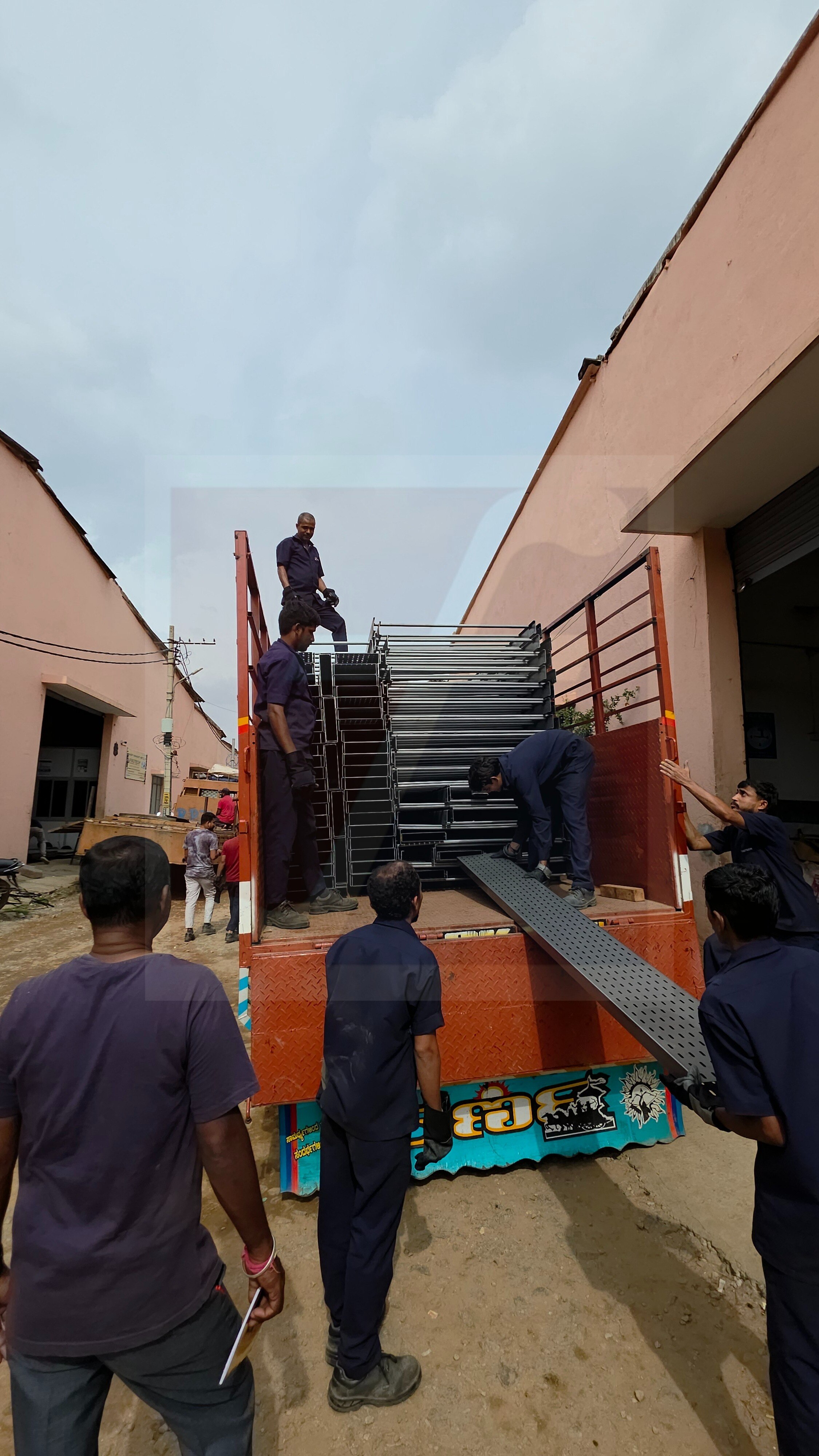
A width change in a cable route affects more than the tray’s outside dimensions: it changes cable space, support loads, joining details, and the path available for future maintenance. By the end, you will be able to identify the correct reducer direction, verify the tray dimensions, plan the installation, and prepare a usable specification for a manufacturer.
Key takeaways
- Match reducer width, height, bend direction, and splice-hole pattern to both tray sections.
- Keep cable bend radius within the cable manufacturer’s stated minimum.
- Use a smooth transition with deburred edges and correctly fitted splice plates.
- Send tray sizes, material, finish, direction, and site dimensions to the manufacturer.
How the reducer fits into a complete tray route
Place the reducer between the wider tray section and the narrower section so the route runs continuously from wide tray, through the transition, into narrow tray. A cable accessories manufacturer uses a raceway tray reducer to preserve the side-rail profile, splice-hole pattern, and cable-support surface across that change.
1. Match the reducer to the connected tray family, including its side-rail geometry, material, finish, joining plates, covers, and dividers. A flat plate only closes unused width; it does not provide a supported, spliceable transition.
2. Choose a straight or concentric reducer when the narrower tray remains centred on the wider route. Choose a left-offset or right-offset reducer when the cable path must stay aligned with one side rail. Specify the offset from the cable’s direction of travel, not from the viewing position at the opposite end.
3. Keep component roles separate. A bend changes direction, a tee branches the route, a cross creates four paths, and a transition to conduit or enclosed raceway changes the containment system. None is interchangeable with a width reducer.
The reducer changes tray width, not the cable’s minimum bend radius. Check the cable manufacturer’s radius where the route approaches an equipment entry, termination, splice, or following bend; a narrow throat can force damage even when both tray sections fit.
A reducer from another tray series can fail at the splice or cover despite having the same nominal widths.
How to choose the direction and specify the reducer dimensions
Choose the reducer direction from the cable’s travel and the existing tray position, viewed along the route—not from “left” or “right” viewed from the opposite end.
| Geometry | What it does | When it applies |
|---|---|---|
| Centered | Reduces both sides evenly | The cable route remains centred |
| Left-sided | Keeps the cable route aligned with the left tray rail | The existing route follows the left side |
| Right-sided | Keeps the cable route aligned with the right tray rail | The existing route follows the right side |
Before ordering a raceway cable tray reducer, record:
- Wider and narrower tray widths
- Tray side height and clear internal cable capacity
- Reducer length
- Flange or joining-hole pattern
- Tray series, material, and finish
- Cover, divider, and splice-hardware requirements
For example, a 300 mm tray reducing to 150 mm needs more than a “300 × 150” description. Check the manufacturer’s drawing for the actual side height, clear internal widths, reducer throat, transition length, and hole locations. Confirm that the 300 mm section and the 150 mm section use the same joining pattern.
Nominal width does not guarantee usable space. Side rails, dividers, cover hardware, and sloping transition metal can narrow the cable path. A reducer from another tray series can therefore fail to fit—or leave cables short of required clearance—even when both products carry the same nominal widths.
How to protect cables and install the transition correctly
A reducer is part of the loaded tray assembly, not a decorative closure. Keep each cable above its manufacturer’s minimum bend radius, preserve power-control separation, and prevent the narrow throat from becoming an overfilled pinch point. Leave room to pull, inspect, and replace cables.
1. Join the wider tray, reducer, and narrower tray with the specified joining plates and bolts. Align side rails and splice holes before tightening; forced alignment can distort the fitting and damage cable jackets. Follow the reducer’s load and span data, not the straight-tray rating.
2. Place supports according to the fitting instructions, using closer supports where the transition concentrates cable weight or side pressure. This matters on heavily loaded, vertical, and ceiling-mounted runs. Do not pull cables across burrs, sharp projections, exposed cut edges, or rough internal surfaces; deburr, smooth, and protect every cut edge.
3. Fit the cover without crushing cables or blocking inspection access. After pulling and rearranging cables, inspect jackets at the throat and both tray ends. If the reducer forces a bundle into a tight turn before a bend, termination, splice, or equipment entry, change the route or fitting.
4. Verify metallic continuity across every joint. Paint, powder coating, corrosion, loose hardware, or a nonconductive splice can interrupt bonding, so install bonding jumpers or another equipment-grounding method when the governing electrical code requires it.
Ask the cable tray reducer manufacturer to confirm compatibility among galvanized steel, aluminum, stainless steel, and coated parts for wet, chemical, or salt-laden exposure; dissimilar metals can create galvanic corrosion.
What changes when the reducer is installed above a ceiling
Above a ceiling, a reducer becomes a supported, accessible raceway transition, not merely a width change. An enclosed or surface-raceway reducer cannot replace an open cable-tray reducer because enclosure, fill, cover, access, support, and fitting requirements belong to the same raceway system.
A ceiling raceway reducer must match the tray series and installation method. Confirm the ceiling construction, suspension rods or other approved attachments, and the combined weight of the reducer, tray, cables, covers, and joining hardware. The transition can concentrate cable weight and side pressure, so use closer supports when the manufacturer’s span data requires them.
Before closing the ceiling, verify:
- Enough vertical and lateral clearance exists for the reducer, cover, bolts, and cable installation tools.
- Lighting, HVAC ducts, sprinkler piping, and other services do not obstruct the tray or its cover.
- The fitting has secure support; do not rely on a suspended ceiling grid or an attachment method intended for wall-mounted raceway.
- The cover can be removed, and a technician can reach the transition for cable pulling, inspection, or replacement.
A narrower route can fit dimensionally and still fail operationally. If it forces cables below their minimum bend radius before a bend, termination, splice, or equipment entry, the reducer is unsuitable. Check the cable bundle’s turning space, not only the tray’s nominal width.
What to send a manufacturer for a buildable reducer specification
Send the manufacturer a buildable specification, not “one reducer for a 300 mm tray.” Include these details:
- Identify the existing tray or raceway series, open or enclosed system type, material, finish, and governing standard or project listing.
- State the wider and narrower widths, side height, clear usable cable capacity, and required reducer length. Use internal clear dimensions, because side rails, dividers, cover hardware, and transition geometry reduce space.
- Define the geometry as centered, left-offset, or right-offset from the cable’s direction of travel. State whether the route must remain aligned with one tray side.
- Specify cover and divider requirements, splice hardware, flange or joining-hole pattern, and any special joining plates or bolts.
- Describe environmental exposure, including indoor, outdoor, wet, corrosive, dusty, or high-temperature locations, and provide the support arrangement at the transition.
- Attach a marked-up route drawing or photographs showing travel direction, adjoining tray ends, dimensions, supports, covers, and nearby bends or equipment entries.
A cable tray reducer manufacturer such as Fixotech Engineering Systems Pvt Ltd: Manufacturer of Cable Management Systems can use this information to check tray-family compatibility, cable capacity, joining geometry, finish, and installation constraints before confirming a specification-based or customized component.
Acceptance checklist:
- Dimensional drawing approved
- Cable bend radius checked
- Support details issued
- Bonding method defined
- Cover and inspection access confirmed
Frequently asked questions
Where does a raceway tray reducer fit in a cable route?
Install it between the wider tray section and the narrower section, using compatible splice plates or connection hardware to maintain a continuous route.
How do you choose the direction and dimensions of a tray reducer?
State whether the reducer is left, right, or centred, then provide the wide and narrow tray widths, side-rail height, length, material, finish, and splice-hole requirements.
How do you protect cables at a tray reducer?
Remove burrs, close sharp gaps, align the cable-support surfaces, and confirm that the transition preserves each cable’s minimum bend radius.
What changes when a reducer is above a ceiling?
Coordinate the reducer with access panels, ceiling clearance, supports, fire-separation requirements, and the space needed to pull or replace cables.
What should you send a cable tray reducer manufacturer?
Send route drawings, tray sizes, reducer direction, transition length, material, finish, load information, cable details, support spacing, and required delivery dimensions.